Hernia prosthesis and method for fabricating same

a technology for prosthesis and hernia, applied in the field of prosthesis, can solve the problems of relative instability of inserter device, serious drawback of the prosthesis, etc., and achieve the effect of greater stability

Active Publication Date: 2011-11-08
BG MEDICAL
View PDF7 Cites 27 Cited by
  • Summary
  • Abstract
  • Description
  • Claims
  • Application Information

AI Technical Summary

Problems solved by technology

The prostheses thus described have a serious drawback related to the relative instability of the inserter device, inside the bag accommodating the prosthesis and also during its removal.

Method used


Image

  • Hernia prosthesis and method for fabricating same
  • Hernia prosthesis and method for fabricating same
  • Hernia prosthesis and method for fabricating same

Examples


Embodiment Construction

[0017]To make the subject matter of the invention more concrete, it is now described in a non-limiting manner in conjunction with the figures of the drawings.

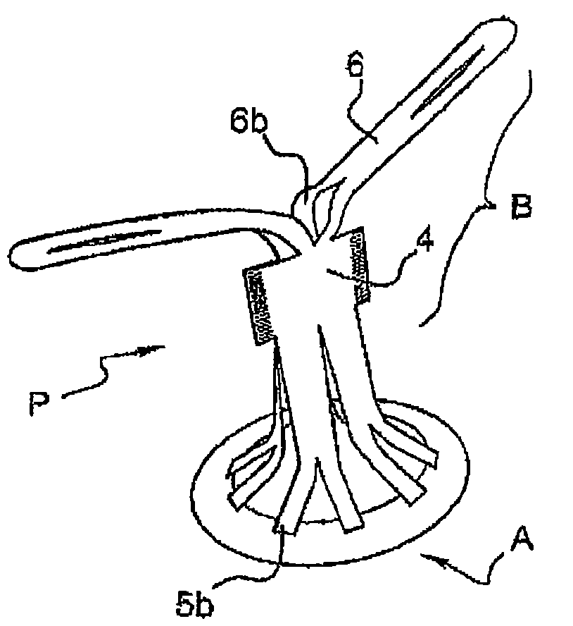
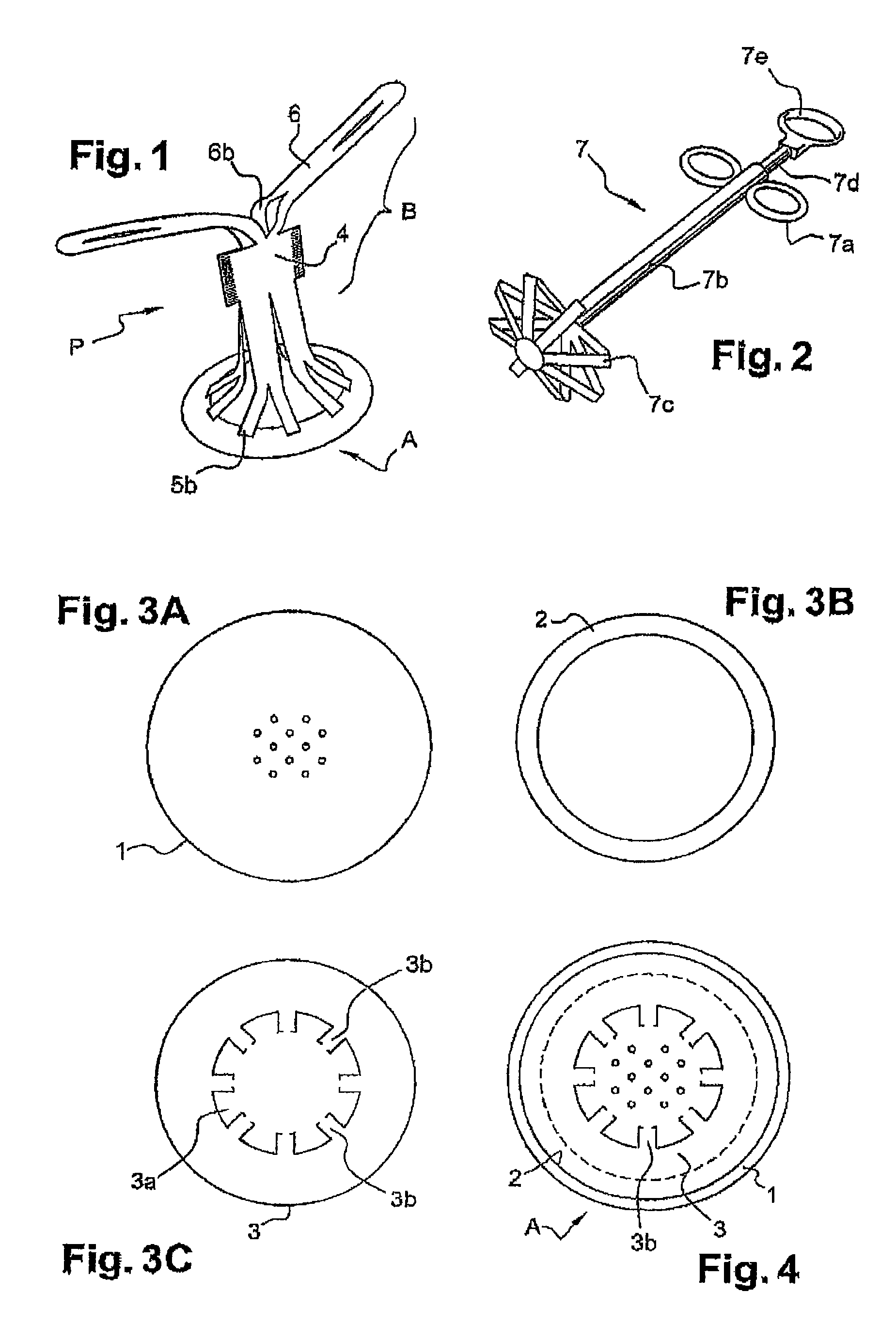
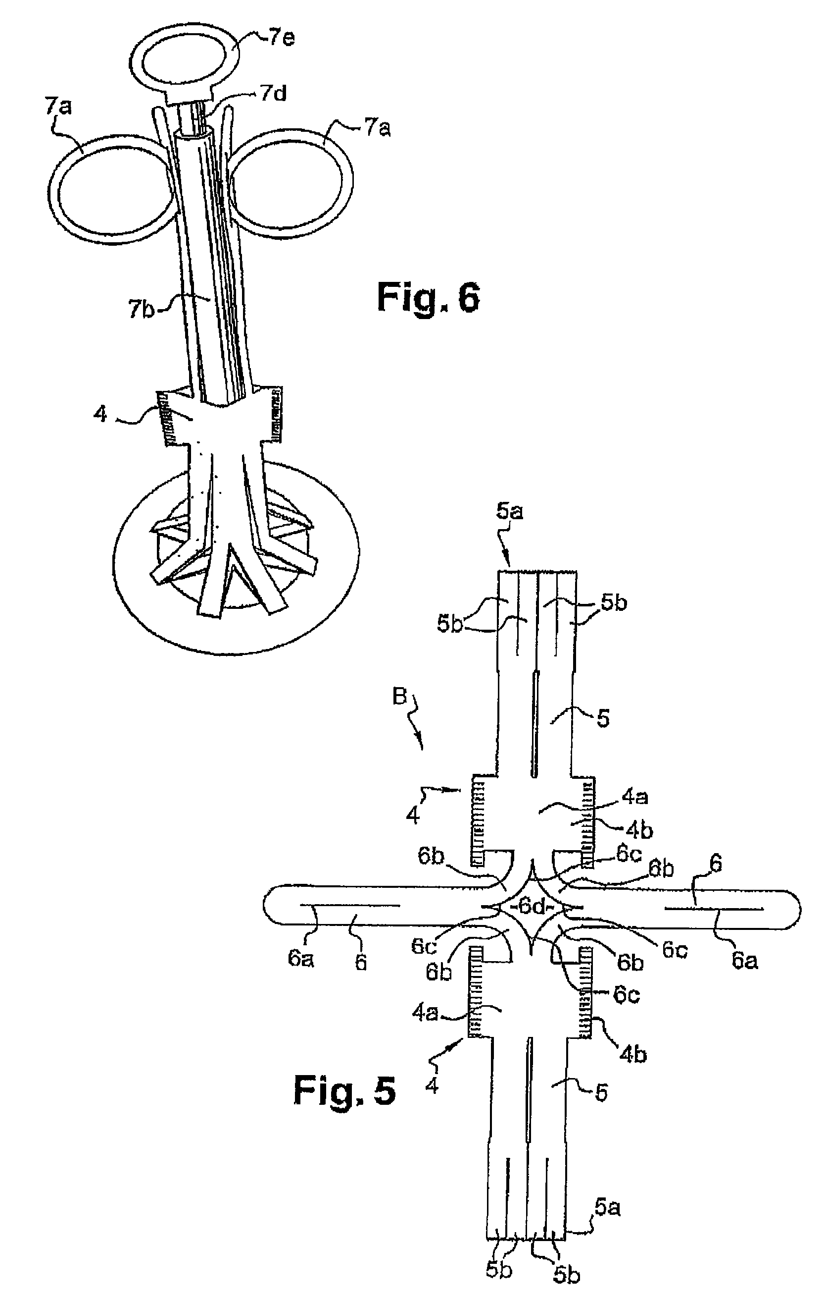
[0018]The hernia prosthesis according to the invention is referred to as a whole by (P). It essentially comprises two joined portions (A-B) made from similar materials and, in particular polypropylene. The first portion (A) constitutes the bag of the prosthesis and comprises a bottom plate (1) having a disc configuration, an annular intermediate connecting plate (2) having the same configuration and disposed at the peripheral edge of the bottom plate, and a top plate (3) having a disc shape, the three components thus described being joined by welding or other joining means, at the peripheral edge. The bottom plate is solid and may, if applicable, have openings for draining the implant site. The top plate has a central opening (3a) forming a neck for the passage and insertion of the inserter device (7). The bottom plate is advan...


PUM


Abstract

A hernia prosthesis includes a first portion defining a bag joined to a second portion constituting a one-piece body. A top plate of the first portion has a plurality of radial tabs around a central opening. The second portion has three distinct successive zones including a first median zone in the form of a very long sheath for introducing and securing an inserter-unfolder device. The median portion is prolonged downwards by a plurality of bands uniformly radially disposed and having bottom ends divided into two each respectively to form two tongues in a Y fastening configuration. Each tongue is fastened by its terminal end to one of the tabs. The second portion, in a top zone, beyond the sheath, comprises two very high tongues which have, in their top portion, a longitudinal slit in their width for attaching the inserter-unfolder device.

Description

CROSS REFERENCE TO RELATED APPLICATIONS[0001]This application claims priority to French application No. 0854306 filed on Jun. 27, 2008, the entire disclosure of this application being hereby incorporated herein by reference.BACKGROUND ART[0002]The invention relates to the technical field of prostheses commonly used for the treatment of umbilical hernias and small eventrations.[0003]This type of prosthesis is well known, together with the inserter device associated with it. Various studies have been conducted and many related patterns have been published. Mention can be made, for example, of US 2007 / 0066980, WO 2004 / 093690, U.S. Pat. No. 7,101,381, US 2006 / 0282105, U.S. Pat. No. 5,258,000 and U.S. Pat. No. 3,857,395.[0004]The prostheses thus described are prepared in the form of a bag having a neck for opening and access to the useful portion of an inserter device prepared in the form of a winged clamp for unfolding by the action of a control rod for inserting and shaping the prosthe...

Claims


Application Information

Patent Timeline
Patent Type & Authority Patents(United States)
IPC IPC(8): A61F2/02
CPCA61F2/0063A61F2002/0072
Inventor DUPIC, ALEXANDRECARTERON, PATRICKWIECEK, WILLIAM
Owner BG MEDICAL
Why Eureka
Try Eureka