Split stream oilfield pumping systems

a technology of oilfield pumping and split stream, which is applied in the direction of fluid removal, earthwork drilling and mining, and wellbore/well accessories, etc., can solve the problems of high repair, replacement and/or maintenance costs of the internal components of the pump, wear out the internal components of the plunger pump, and low overall life of the pump. achieve the effect of increasing the useful life of the clean pump

Active Publication Date: 2011-11-15
SCHLUMBERGER TECH CORP
View PDF18 Cites 114 Cited by
  • Summary
  • Abstract
  • Description
  • Claims
  • Application Information

AI Technical Summary

Benefits of technology

In one embodiment, the present invention includes splitting a fracturing fluid stream into a clean stream having a minimal amount of solids and a dirty stream having solids in a fluid carrier, wherein the clean stream is pumped from the well surface to a wellbore by one or more clean pumps and the dirty stream is pumped from the well surface to a wellbore by one or more dirty pumps, thus greatly increasing the useful life of the clean pumps.

Problems solved by technology

However, the abrasive nature of fracturing fluids is not only effective in breaking up underground rock formations to create fractures therein, it also tends to wear out the internal components of the plunger pumps that are used to pump it.
Thus, when plunger pumps are used to pump fracturing fluids, the repair, replacement and / or maintenance expenses for the internal components of the pumps are extremely high, and the overall life expectancy of the pumps is low.
For example, when a plunger pump is used to pump a fracturing fluid, the pump fluid end, valves, valve seats, packings, and plungers require frequent maintenance and / or replacement.
Such a replacement of the fluid end is extremely expensive, not only because the fluid end itself is expensive, but also due to the difficulty and timeliness required to perform the replacement.
Valves, on the other hand are relatively inexpensive and relatively easy to replace, but require such frequent replacements that they comprise a large percentage of plunger pump maintenance expenses.
In addition, when a valve fails, the valve seat is often damaged as well, and seats are much more difficult to replace than valves due to the very large forces required to pull them out of the fluid end.

Method used


Image

  • Split stream oilfield pumping systems
  • Split stream oilfield pumping systems
  • Split stream oilfield pumping systems

Examples


Embodiment Construction

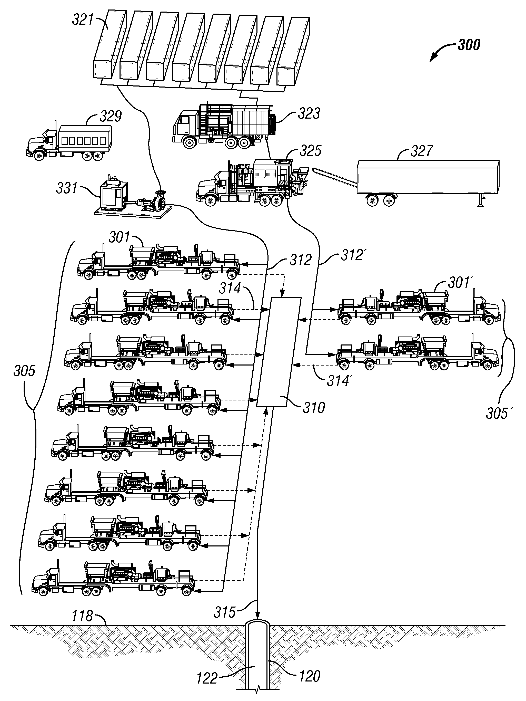
Embodiments of the present invention relate generally to a pumping system for pumping a fluid from a surface of a well to a wellbore at high pressures, and more particularly to such a system that includes splitting the fluid into a clean stream having a minimal amount of solids and a dirty stream having solids in a fluid carrier. In one embodiment, both the clean stream and the dirty stream are pumped by the same type of pump. For example, in one embodiment one or more plunger pumps are used to pump each fluid stream. In another embodiment, the clean stream and the dirty stream are pumped by different types of pumps. For example, in one embodiment one or more plunger pumps are used to pump the dirty stream and one or more horizontal pumps (such as a centrifugal pump or a progressive cavity pump) are used to pump the clean fluid stream.

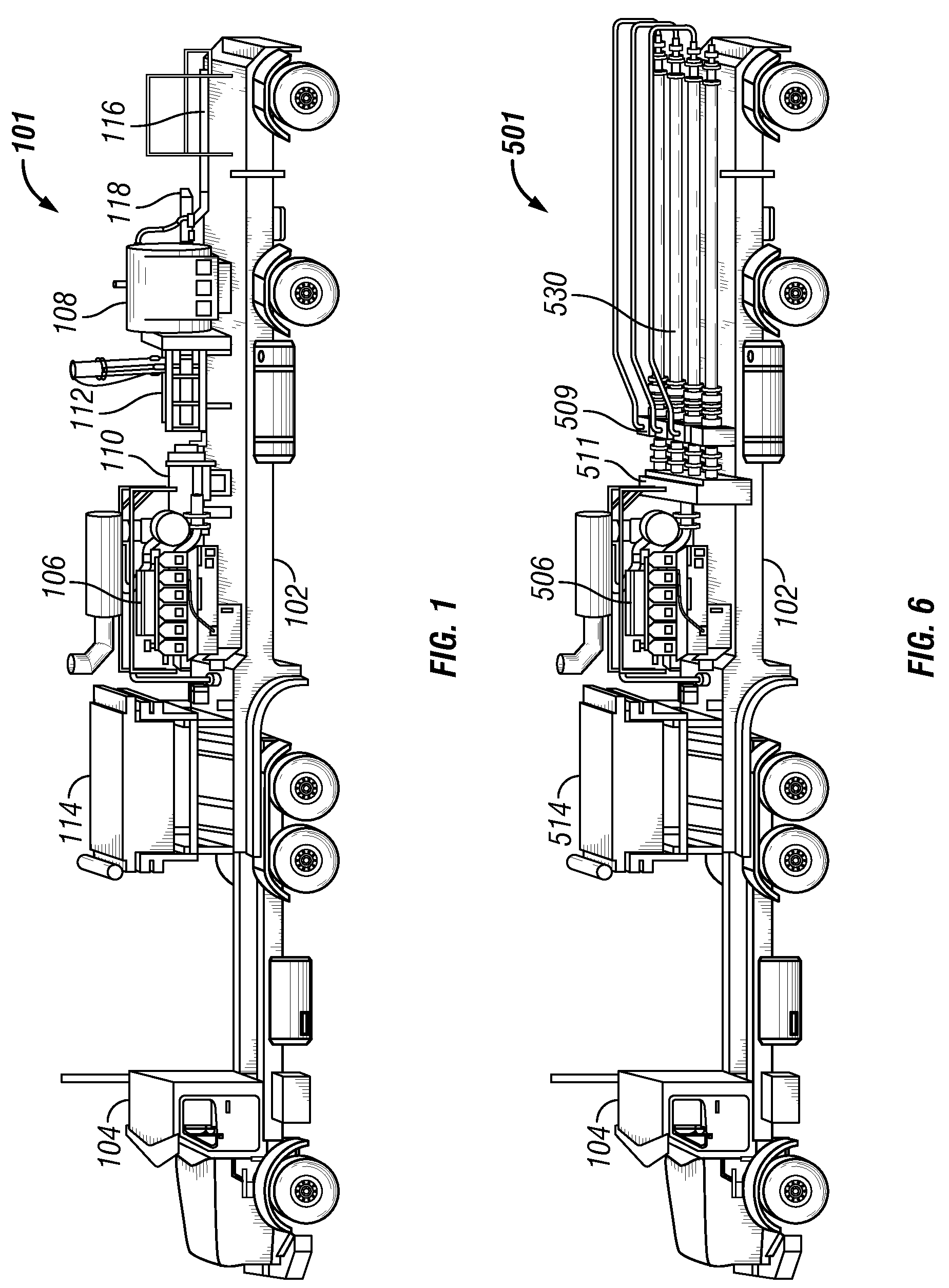
FIG. 1 shows a plunger pump 101 for pumping a fluid from a well surface to a wellbore. As shown, the plunger pump 101 is mounted on a standard trailer...


PUM


Abstract

A method of pumping an oilfield fluid from a well surface to a wellbore is provided that includes providing a clean stream; operating one or more clean pumps to pump the clean stream from the well surface to the wellbore; providing a dirty stream including a solid material disposed in a fluid carrier; and operating one or more dirty pumps to pump the dirty stream from the well surface to the wellbore, wherein the clean stream and the dirty stream together form said oilfield fluid.

Description

FIELD OF THE INVENTIONThe present invention relates generally to a pumping system for pumping a fluid from a surface of a well to a wellbore at high pressure, and more particularly to a such a system that includes splitting the fluid into a clean stream having a minimal amount of solids and a dirty stream having solids in a fluid carrier.BACKGROUNDIn special oilfield applications, pump assemblies are used to pump a fluid from the surface of the well to a wellbore at extremely high pressures. Such applications include hydraulic fracturing, cementing, and pumping through coiled tubing, among other applications. In the example of a hydraulic fracturing operation, a multi-pump assembly is often employed to direct an abrasive containing fluid, or fracturing fluid, through a wellbore and into targeted regions of the wellbore to create side “fractures” in the wellbore. To create such fractures, the fracturing fluid is pumped at extremely high pressures, sometimes in the range of 10,000 to ...

Claims


Application Information

Patent Timeline
Patent Type & Authority Patents(United States)
IPC IPC(8): E21B43/04E21B43/267
CPCE21B43/267E21B43/25E21B43/16E21B43/2607
Inventor SHAMPINE, RODDWYER, PAULSTOVER, RONNIELLOYD, MIKEPESSIN, JEAN-LOUISLEUGEMORS, EDWARDWELCH, LARRY D.HUBENSCHMIDT, JOEGAMBIER, PHILIPPEHUEY, WILLIAM TROYALLAN, TOM
Owner SCHLUMBERGER TECH CORP
Why Eureka
Try Eureka