Perforation acoustic muffler assembly and method of reducing noise transmission through objects

a technology of acoustic muffler and perforation, which is applied in the field of attenuating noise systems, can solve the problems of noise entering the room or space, adverse impact on the transmission loss, etc., and achieve the effect of allowing heat dissipation

Active Publication Date: 2011-11-22
NOISEOUT
View PDF19 Cites 3 Cited by
  • Summary
  • Abstract
  • Description
  • Claims
  • Application Information

AI Technical Summary

Benefits of technology

[0008]In response to the foregoing challenges, applicant has developed an innovative noise attenuation system for use in a structure having a hole for some type of mechanism, such as a recessed light fixture mounted therein, which cannot be addressed with a complete acoustic enclosure, due to required air flow for heat dissipation, or a needed opening, such as when a large quantity of wires is required. The noise attenuation system is constructed to permit the absorption of noise emitted into the structure from the mechanism such that the transmission loss of the structure is not adversely impacted by the presence of the opening and the mechanism located therein. The noise attenuation system is also constructed to permit dissipation of heat from the mechanism, if required. The noise attenuation includes a noise absorbing muffler positioned within the structure in an area substantially surrounding the mechanism. The noise absorbing muffler includes an outer high STC barrier layer that limits the passage of sound waves emitted from the mechanism therethrough. The noise absorbing muffler further includes a noise absorbing layer positioned adjacent to the outer barrier layer. The noise absorbing layer absorbs a predetermined amount of sounds waves emitted from the mechanism. An optional third layer can be secured to the barrier layer, which would be a noise decoupling layer. This is most commonly used when low frequency noise may need to be decoupled from the structure.

Problems solved by technology

While the walls, floors and ceilings can be adequately insulated to limit noise transmission, these openings have an adverse impact on the transmission loss.
As such, noise can enter the room or space through the opening and the device mounted therein.

Method used


Image

  • Perforation acoustic muffler assembly and method of reducing noise transmission through objects
  • Perforation acoustic muffler assembly and method of reducing noise transmission through objects
  • Perforation acoustic muffler assembly and method of reducing noise transmission through objects

Examples


example 1

[0024]The frequency f of concern is 500 Hz. The velocity of the sound wave vw is 1100 ft / sec. Using this information, the approximate desired length of the muffler 11 can be determined.

λ=1100 ft / sec / 500 Hz=2.2 ft

The NRC coefficient for a material for using in absorbing sound waves with a frequency f of 500 Hz is 0.85.

β=2λ / NRC=2(2.2 ft) / 0.85=5.2 ft

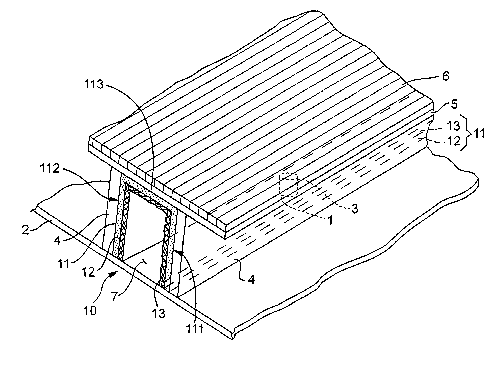
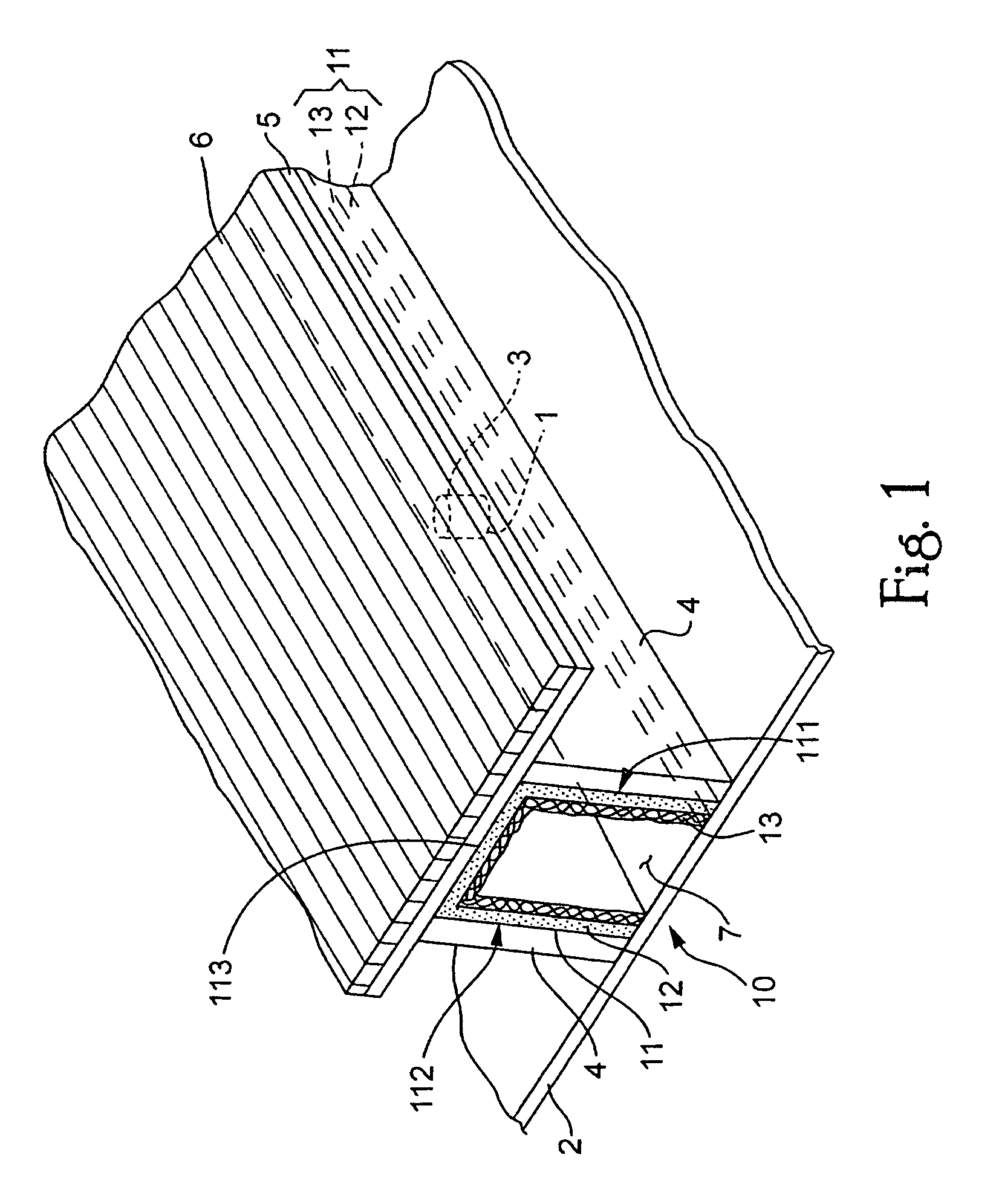
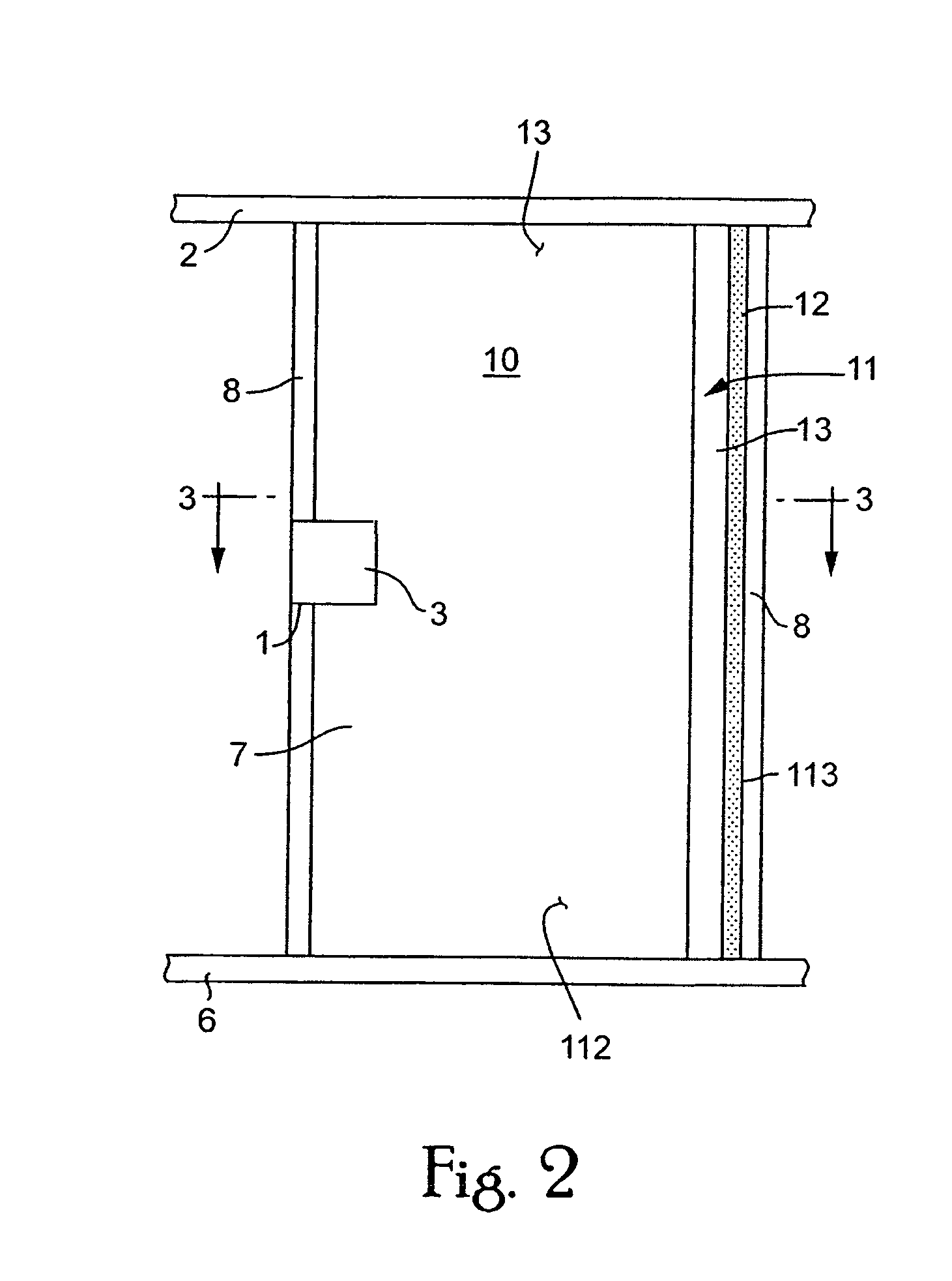
The minimum length of the muffler 11 is approximately 5.2 ft with the mechanism 3 being located approximately in the center of the muffler 11 (i.e., ½β as shown in FIG. 4). This determined minimum length of the muffler 11 will provide adequate noise attenuation whereby the sound waves will be absorbed prior to exiting the muffler 11 and can provide sufficient space to permit ventilation of the mechanism 3 and dissipation of any heat emitted from the mechanism 3.

example 2

[0025]The frequency f of concern is 125 Hz. The velocity of the sound wave vw is 1000 ft / sec. Using this information, the approximate length of the muffler 11 can be determined.

λ=1100 ft / sec / 125 Hz=8.8 ft

The NRC coefficient for a material for using in absorbing sound waves with a frequency f of 125 Hz is 0.65.

β=2λ / NRC=2(8.8 ft) / 0.65=27 ft

The minimum length of the muffler 11 is approximately 27 ft with the mechanism 3 being located approximately in the center of the muffler 11 (i.e., ½β as shown in FIG. 4). This determined length of the muffler 11 will provide adequate noise attenuation whereby the sound waves will be absorbed prior to exiting the muffler 11 and can provide sufficient space to permit ventilation of the mechanism 3 and dissipation of any heat emitted from the mechanism 3.

[0026]The equation for β above will result in muffler 11 absorbing substantially all of the noise generated by mechanism 3. However, ceiling 2, wall 8, joists 4, etc. will not block all of the noise g...


PUM

PropertyMeasurementUnit
velocityaaaaaaaaaa
frequencyaaaaaaaaaa
lengthaaaaaaaaaa

Abstract

A noise attenuation system is disclosed for use in a structure having a recessed fixture mounted therein or other unit which creates a hole in the structure in which it is secured, such as a ceiling. The noise attenuation system is constructed to permit the absorption of noise emitted into the structure from the mechanism. The noise attenuation includes a noise absorbing muffler positioned within the structure in an area substantially surrounding the mechanism. The noise absorbing layer includes an outer barrier layer that limits the passage of sound waves emitted from the mechanism therethrough. The noise absorbing muffler further includes a noise absorbing layer positioned adjacent the outer barrier layer. The noise absorbing layer absorbs a predetermined amount of sounds waves emitted from the recessed fixture. Additionally, an optional noise absorbing layer, or equivalent decoupling material can be included to decouple the barrier from the structure for low frequency noises.

Description

[0001]This application is a continuation-in-part of U.S. application Ser. No. 11 / 017,642, filed Dec. 22, 2004, which, in turn, is based on and derives the benefit of the filing date of U.S. Provisional Patent Application No. 60 / 530,981, filed Dec. 22, 2003. The contents of both of these applications are incorporated herein by reference.BACKGROUND OF THE INVENTION[0002]1. Field of the Invention[0003]The present invention relates to a system for attenuating noise. In particular, the present invention relates to a system for attenuating noise that may be emitted from a room through a hole or opening. Additionally, the invention can attenuate noise when the opening houses any low STC object that cannot be completely enclosed, such as a recessed light fixture. The present invention further relates to a methodology for attenuating noise from a room that contains at least one hole or opening for receiving a low STC object that cannot be completely enclosed, such as a recessed light fixture...

Claims


Application Information

Patent Timeline
Patent Type & Authority Patents(United States)
IPC IPC(8): G10K11/168
CPCG10K11/168B32B5/024B32B5/24B32B7/12B32B1/00E04B1/82B32B2419/00B32B2262/101B32B2262/108B32B2307/10B32B2307/30B32B2307/3065
Inventor SCHNITTA, BONNIE S
Owner NOISEOUT
Why Eureka
Try Eureka