Suture anchor

a technology of suture anchors and anchors, which is applied in the field of suture anchors, can solve the problems of prolonged pain and recovery time, loss of the ability to elevate and externally rotate the arm, and difficulty in manipulating sutures within the surgical site using arthroscopic techniques

Active Publication Date: 2011-11-22
SCOTT W TATE
View PDF171 Cites 176 Cited by
  • Summary
  • Abstract
  • Description
  • Claims
  • Application Information

AI Technical Summary

Problems solved by technology

One common example is a torn rotator cuff, where the supraspinatus tendon has separated from the humerus causing pain and loss of ability to elevate and externally rotate the arm.
Such large incision procedures are traumatic, causing prolonged pain and recovery time.
However, it is difficult to manipulate sutures within the surgical site using arthroscopic techniques.
In addition, when knot tying is used to secure the suture to a bone anchor, it is difficult to properly adjust the tension of the suture while tightening the knot.

Method used


Image

  • Suture anchor
  • Suture anchor
  • Suture anchor

Examples


Embodiment Construction

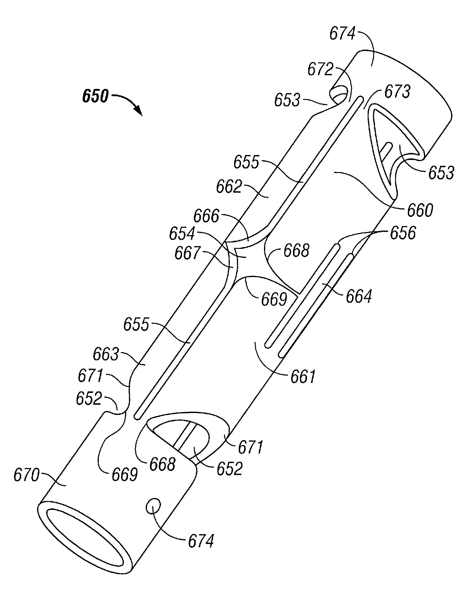
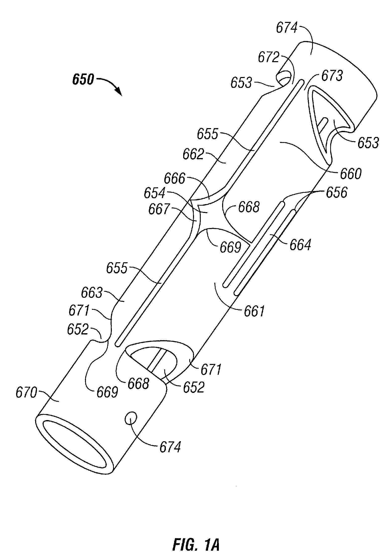
[0040]Various embodiments include a bone anchor constructed in such a manner that the bone anchor may have one of two configurations. A first low-profile configuration allows the anchor to be easily inserted into bone. In one embodiment, the bone anchor is inserted into a pre-drilled bone hole. In other embodiments, the bone anchor is inserted directly into bone without pre-drilling. In one embodiment, the bone anchor is inserted by tapping the anchor into the bone. In other embodiments, the bone anchor is inserted by applying a constant axial force to the anchor. In still other embodiments, the bone anchor is inserted by screwing the anchor into the bone. A second configuration of the bone anchor has a larger profile such that the anchor cannot be easily removed from the bone after insertion. In one embodiment, the second configuration is achieved by deploying one or more lateral features that extend laterally away from the axis of the bone anchor. The lateral features prevent the ...


PUM


Abstract

A bone anchor is described having pre-attached suture material. After insertion, lateral wings can be deployed on the bone anchor to prevent anchor pull-out. The suture may be attached at the tip of the anchor by tying it to a wire hook secured in a cavity in the anchor tip. The anchor may be inserted and deployed using an anchor inserter that is configured to apply an axial force to the anchor, thereby deforming the anchor to form the lateral wings.

Description

CROSS-REFERENCE TO RELATED APPLICATIONS[0001]This application is a continuation-in-part of U.S. application Ser. No. 11 / 143,007, now U.S. Pat. No. 7,585,311, filed Jun. 1, 2005, which claims the benefit of U.S. Provisional Application Nos. 60 / 576,477, filed Jun. 2, 2004; 60 / 610,924, filed Sep. 17, 2004; and 60 / 634,174, filed Dec. 7, 2004. This application also claims the benefit of U.S. Provisional Application No. 60 / 753,445, filed Dec. 22, 2005. All of these applications are incorporated herein by reference in their entirety.BACKGROUND OF THE INVENTION[0002]1. Field of the Invention[0003]The present invention relates to medical devices and procedures. More particularly, the present invention relates to suture anchors for insertion into bone.[0004]2. Description of the Related Art[0005]There are several medical procedures where a surgeon needs to have suture material that is secured to bone. For example, the surgeon may desire bone-anchored suture to attach soft tissue such as tendo...

Claims


Application Information

Patent Timeline
Patent Type & Authority Patents(United States)
IPC IPC(8): A61B17/04
CPCA61B17/0401A61B17/0469A61B17/0483A61B2017/00986A61B2017/0409A61B2017/0412A61B2017/0414A61B2017/0417A61B2017/042A61B2017/0422A61B2017/0454A61B2017/0458
Inventor GREEN, MICHAEL L.BOJANOWSKI, BARTTAURO, JOSEPH C.GREELIS, JOHN P.HEAVEN, MALCOLM
Owner SCOTT W TATE
Why Eureka
Try Eureka