Droplet compartmentalization for chemical separation and on-line sampling

a chemical separation and droplet technology, applied in the field of droplet compartmentalization for chemical separation and online sampling, can solve the problems of insufficient simpleness, inability to maintain the contents of the separated peaks, and inability to easily preserve the integrity of the separated components for additional analysis or manipulation

Inactive Publication Date: 2011-11-22
UNIV OF WASHINGTON
View PDF4 Cites 22 Cited by
  • Summary
  • Abstract
  • Description
  • Claims
  • Application Information

AI Technical Summary

Problems solved by technology

The basic unit of a biological system is a single cell, and malfunctions at the single-cell level can result in devastating diseases, such as in cancer metastasis, where a single cell seeds the formation of a distant tumor.
For many single-cell studies, it is insufficient simply to detect a series of separated peaks using fluorescence.
After the detection of each band, however, the integrity of the separated components cannot be easily preserved for additional analysis or manipulation, owing to molecular diffusion.
This challenge is especially acute in high-resolution liquid separation techniques, such as in capillary electrophoresis (CE) and microscale high-performance liquid chromatography (HPLC), because of the extremely small volumes and narrow bands involved and because molecular diffusion scales quadratically with the inverse of distance.
In such systems, it is extremely difficult to maintain the contents of the separated peaks after their detection.
The methods currently employed to test such real-time reaction profiles have not provided a sufficient solution to the issues of dispersion and the inaccuracies in the resulting analyses that result from such dispersion.
In addition to sample dilution due to dispersion and diffusion effects, sample integrity in on-line sampling can be further compromised by contaminates deposited on the channel wall of the device during prior sample testing.

Method used


Image

  • Droplet compartmentalization for chemical separation and on-line sampling
  • Droplet compartmentalization for chemical separation and on-line sampling
  • Droplet compartmentalization for chemical separation and on-line sampling

Examples


example 1

Droplet Formation and Analysis of Liquid Separated by Capillary Electrophoresis

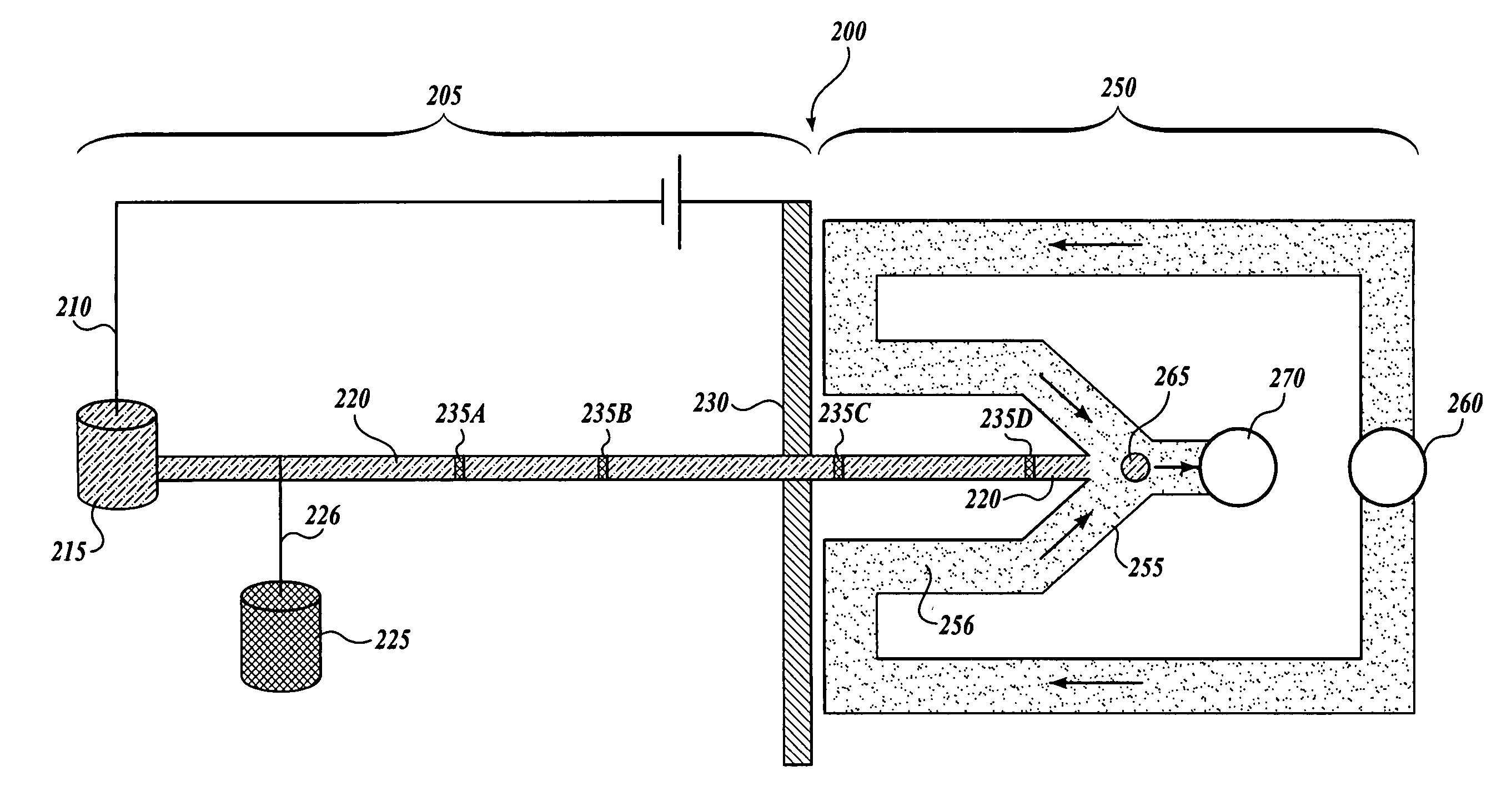
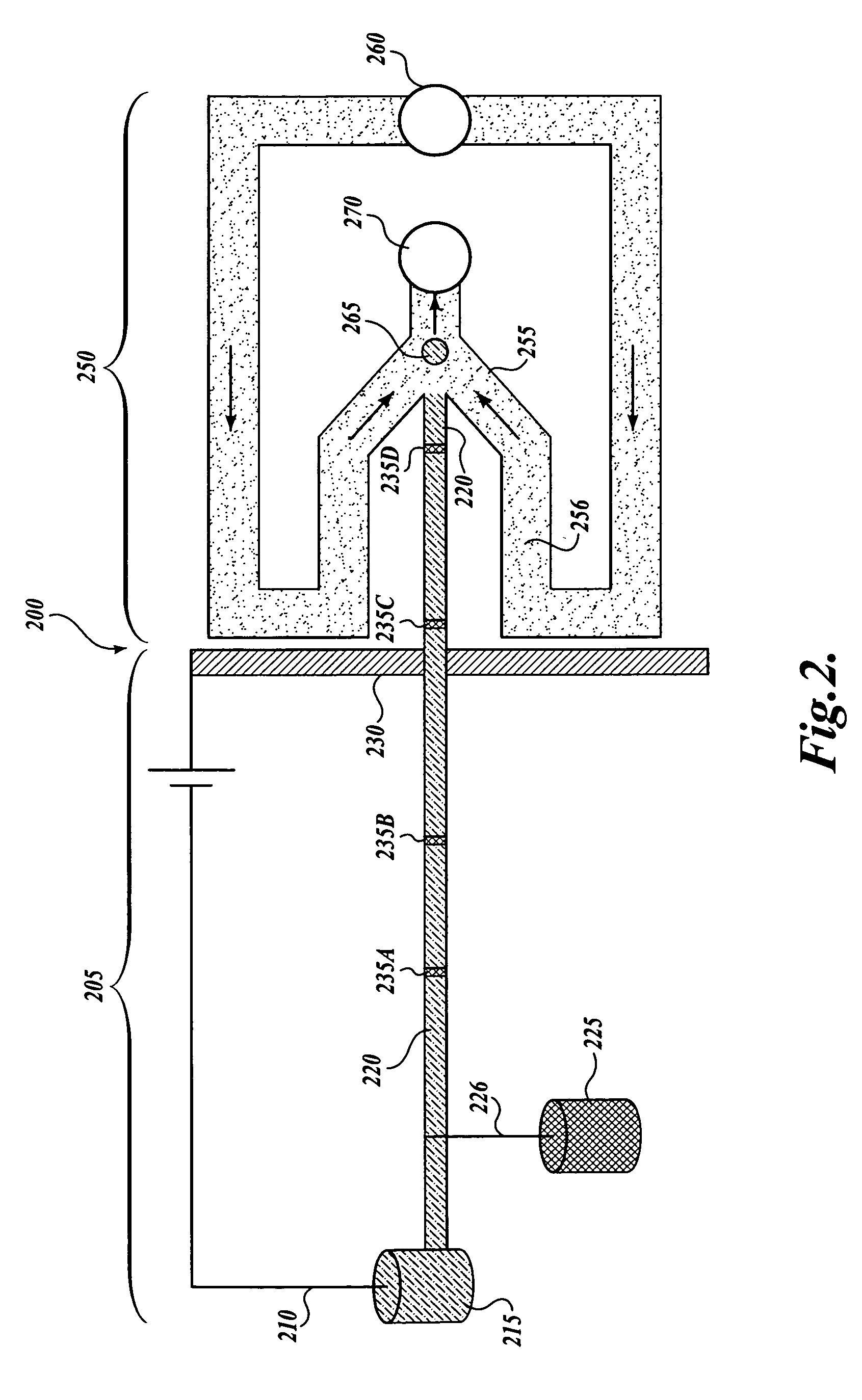
[0071]A fluidic-device design similar to that illustrated in FIG. 2 was used to compartmentalize CE-separated bands of analyte. The device was fabricated in polydimethylsiloxane (PDMS) and consisted of three regions: (1) a sample injection region, (2) a CE separation channel, and (3) a droplet formation region. The sample-injection channel was 3 μm by 3 μm cross-section and served as a fluidic resistor between the sample reservoir and the CE separation channel. Injection of a sample plug into the CE channel was achieved using a “screw valve” to press down on the sample-injection channel. The screw was “closed” (i.e., pressed down to block off the channel) before and after injection, thus the pressure remained balanced and the sample solution was unable to bleed into the separation channel during CE.

[0072]The CE channel cross-section was 10 μm×10 μm. The droplet formation region was comprised of two oil ch...

example 2

Droplet Immobilization

[0080]Depending on the application, droplets might be further analyzed on-chip or removed off-chip for additional separation or assay. For further on-chip analysis, optical and electrochemical techniques are typically useful for analysis, but for these techniques the droplets need to be docked and stored in a spatially defined manner after chemical separation. Droplets were generated in this experiment with a device similar to that of FIG. 2.

[0081]To facilitate docking of droplets, a device was fabricated similar to the device of FIG. 4A with tall and wide channels with alcoves (50 μm×75 μm), where droplets flowed and docked, and small constricted channels (10 μm×10 μm), that allowed for liquid flow through the alcoves but which prevented the droplets from passing through, as illustrated in FIG. 9A. In the absence of droplets, the flow path through the small constricted channel offers less flow resistance than the path down the larger channel. As a result, a dr...


PUM

PropertyMeasurementUnit
volumeaaaaaaaaaa
volumeaaaaaaaaaa
volumeaaaaaaaaaa

Abstract

Methods and devices are provided for overcoming detrimental diffusive effects in a sample liquid stream by forming segmented liquid bodies (e.g., droplets) from a sample liquid stream in an immiscible liquid stream. The liquid bodies are formed at the intersection of a channel providing the sample liquid stream and a channel providing the immiscible liquid stream. The formed liquid bodies compartmentalize the portion of the sample liquid stream from which the liquid bodies are formed, thus minimizing the detrimental effects of diffusion that occur in a continuous liquid stream.

Description

CROSS-REFERENCE TO RELATED APPLICATION[0001]This application claims the benefit of U.S. Provisional Application No. 61 / 033,281, filed Mar. 3, 2008, expressly incorporated herein by reference in its entirety.STATEMENT OF GOVERNMENT LICENSE RIGHTS[0002]This invention was made with Government support under Grant No. EB005197 awarded by the National Institutes of Health. The Government has certain rights in the invention.BACKGROUND OF THE INVENTION[0003]The basic unit of a biological system is a single cell, and malfunctions at the single-cell level can result in devastating diseases, such as in cancer metastasis, where a single cell seeds the formation of a distant tumor. Given that a single cell contains a diverse set of molecules at low copy numbers, high-resolution and high-sensitivity techniques in microscale chemical separation play an important role in single-cell analysis. For many single-cell studies, it is insufficient simply to detect a series of separated peaks using fluores...

Claims


Application Information

Patent Timeline
Patent Type & Authority Patents(United States)
IPC IPC(8): G01N1/18
CPCG01N27/44717G01N30/16Y10T436/25Y10T436/118339B01L2400/0421B01L2400/0487B01L3/502784B01L3/502753B01L2400/0415B01L2200/0668B01L2400/0439
Inventor CHIU, DANIEL T.EDGAR, JOHN SCOTT
Owner UNIV OF WASHINGTON
Why Eureka
Try Eureka