Eureka AIR delivers breakthrough ideas for toughest innovation challenges, trusted by R&D personnel around the world.

Dummy pattern design for reducing device performance drift

a technology of mos devices and dummy patterns, applied in the field of integrated circuits, can solve the problems of drive current drift has to be compensated, and non-uniform drive current drift, and achieve the effect of reducing the variation of stresses applied to mos devices

Inactive Publication Date: 2011-06-07
TAIWAN SEMICON MFG CO LTD
View PDF14 Cites 118 Cited by
  • Summary
  • Abstract
  • Description
  • Claims
  • Application Information

AI Technical Summary

Benefits of technology

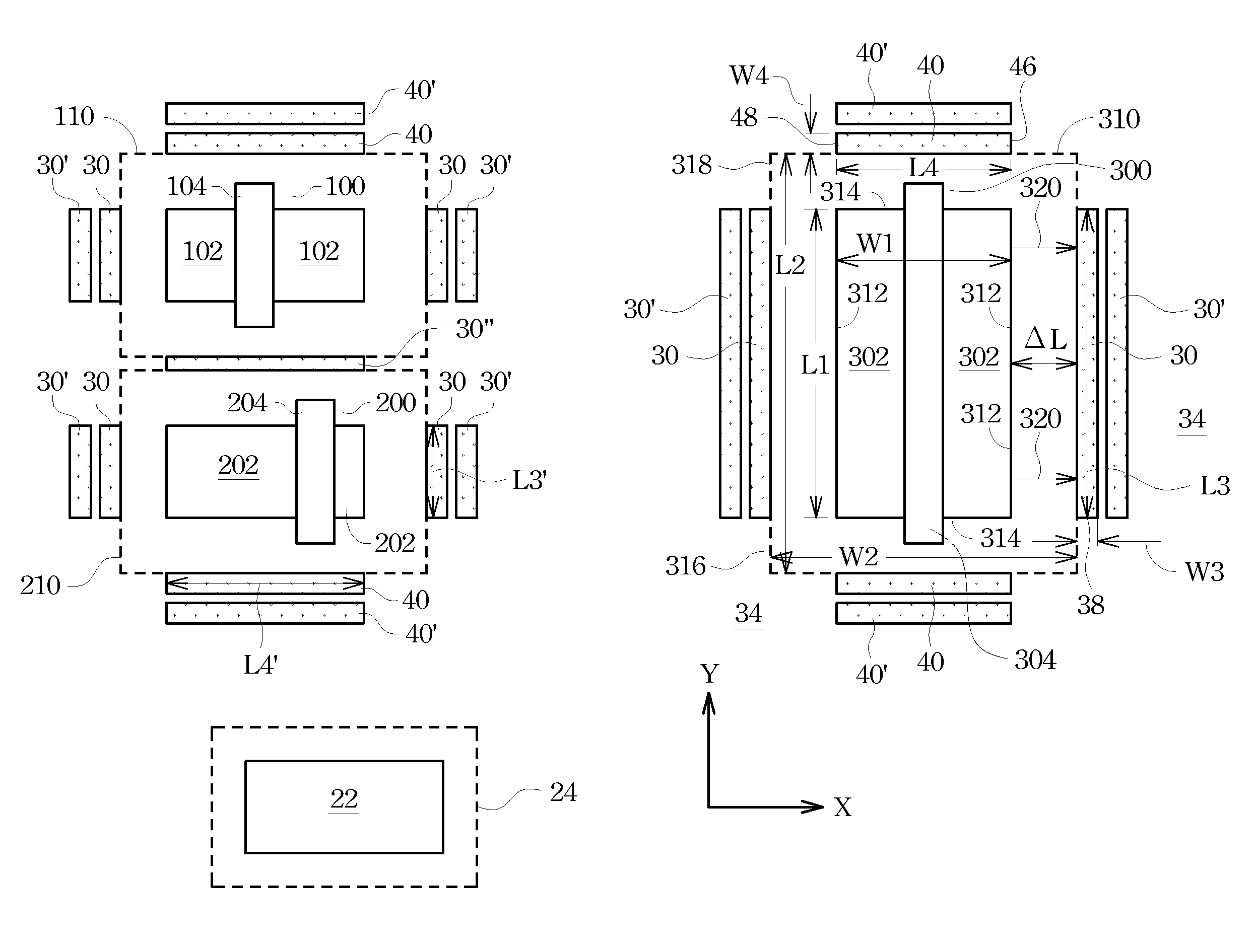
[0012]The advantageous features of the present invention include added dummy diffusion regions for blocking stress-application paths, and hence the variations in the stresses applied to MOS devices are reduced.

Problems solved by technology

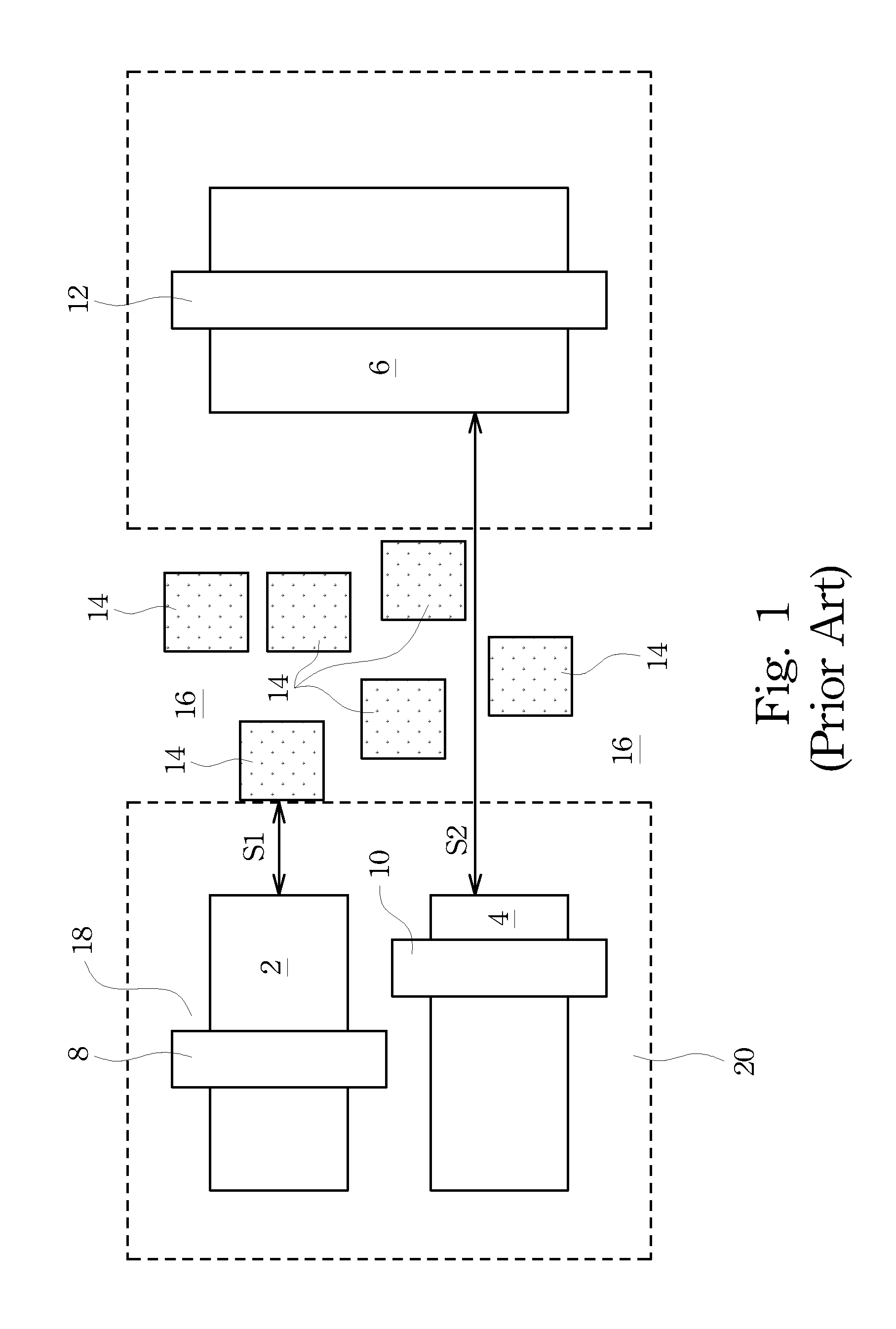
Accordingly, the drive current improvements for different MOS devices may be different, resulting in non-uniform drive currents, and hence non-uniform drive current drifts.
However, with the non-uniform drive current drift, during the simulations of the circuit design, the drive current drift has to be compensated for.
What makes the compensation of the drive current drift complicated is that the stresses of MOS devices are affected by various factors and those factors behave differently for different layouts.
Conventional integrated circuit designs, however, often neglected such an issue.

Method used


Image

  • Dummy pattern design for reducing device performance drift
  • Dummy pattern design for reducing device performance drift
  • Dummy pattern design for reducing device performance drift

Examples


Embodiment Construction

[0016]The making and using of the presently preferred embodiments are discussed in detail below. It should be appreciated, however, that the present invention provides many applicable inventive concepts that can be embodied in a wide variety of specific contexts. The specific embodiments discussed are merely illustrative of specific ways to make and use the invention, and do not limit the scope of the invention.

[0017]A method for inserting dummy patterns into layouts of integrated circuits is provided. The intermediate stages of the method are provided, and the variations of the method are also discussed. Throughout the various views and illustrative embodiments of the present invention, like reference numbers are used to designate like elements.

[0018]For each of the MOS devices in a semiconductor chip, the respective spacings from other MOS devices affect its performance. The spacings may be filled with shallow trench isolation (STI) regions (or field regions). Due to the inherent ...


PUM


Abstract

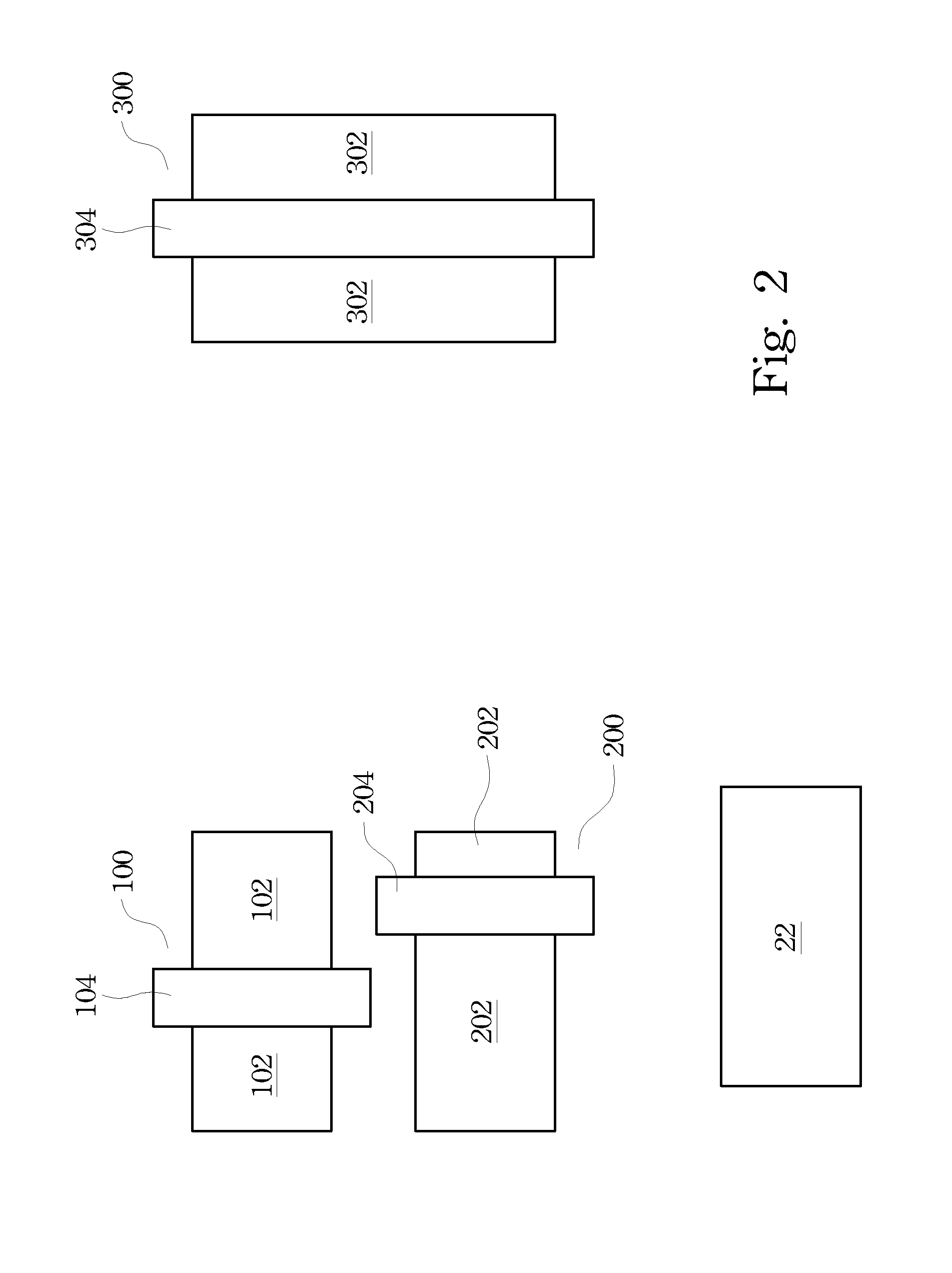
A method of forming an integrated circuit structure on a chip includes extracting an active pattern including a diffusion region; enlarging the active pattern to form a dummy-forbidden region having a first edge and a second edge perpendicular to each other; and adding stress-blocking dummy diffusion regions throughout the chip, which includes adding a first stress-blocking dummy diffusion region adjacent and substantially parallel to the first edge of the dummy-forbidden region; and adding a second stress-blocking dummy diffusion region adjacent and substantially parallel to the second edge of the dummy-forbidden region. The method further includes, after the step of adding the stress-blocking dummy diffusion regions throughout the chip, adding general dummy diffusion regions into remaining spacings of the chip.

Description

[0001]This application claims the benefit of U.S. Provisional Patent Application Ser. No. 61 / 051,460, filed May 8, 2008, and entitled “Dummy Patterns in Semiconductor Process,” which application is hereby incorporated herein by reference.TECHNICAL FIELD[0002]This invention relates generally to integrated circuits, and more particularly to metal-oxide-semiconductor (MOS) devices, and even more particularly to a dummy pattern design for reducing the performance drift of the MOS devices caused by differences in stresses applied on the MOS devices.BACKGROUND[0003]It is well known that the drive currents of metal-oxide-semiconductor (MOS) devices are affected by the stresses applied on their channel regions. The stresses in the channel regions may improve the carrier mobility. Generally, it is desirable to induce a tensile stress in the channel region of an n-type MOS (NMOS) device, and to induce a compressive stress in the channel region of a p-type MOS (PMOS) device.[0004]Although the ...

Claims


Application Information

Patent Timeline
Patent Type & Authority Patents(United States)
IPC IPC(8): G06F17/50G06F19/00
CPCH01L27/0207G06F2217/12G06F2119/18Y02P90/02
Inventor LU, LEE-CHUNGKUO, CHIEN-CHIHLI, JIAN-YIYANG, SHENG-JIER
Owner TAIWAN SEMICON MFG CO LTD
Why Eureka
Eureka Blog
Learn More