System and method for the diffusion of illumination produced by discrete light sources

a discrete light source and diffusion technology, applied in the field of lighting, can solve the problems of unfavorable illumination hot spots perception, uneven luminance distribution, and limited illumination, and achieve the effect of reducing the size of the plastic tubing to a minimum of approximately 20 mm, and reducing the visual intrusion of the configuration

Active Publication Date: 2007-08-14
SIGNIFY HLDG BV
View PDF20 Cites 121 Cited by
  • Summary
  • Abstract
  • Description
  • Claims
  • Application Information

AI Technical Summary

Problems solved by technology

The disadvantage of these products is that the light emitting diodes constitute point sources of light and in order to ensure an even luminance distribution along the length of the tube, this tube must incorporate some means of diffusing the light.
A second disadvantage of this type of diffuser, is that the plastic tubing must have sufficient cross-sectional area such that the distance between the light emitting diodes and the inner wall of the tubing is sufficient to enable even distribution of light and hence an even luminance distribution along the length of the tube.
Failure to observe this requirement can result in an uneven luminance distribution and the perception of illumination hot spots.
This combination of limitations and requirements, in addition to economic constraints on the number of light emitting diodes per unit length, which directly affects the spacing, D 10, practically limits the diameter of the plastic tubing to a minimum of approximately 20 mm.
A minimum diameter of 20 mm can be acceptable for outdoor applications, however this configuration can be visually intrusive for many indoor applications, in particular for retail displays and shop window delineation.
Thus this method of creating an even linear illumination does not achieve a sufficiently thin line of light for a number of applications.
In addition, the length of the light line created is limited by the constraints on the length of the mold used to create the light guides.
While these methods and apparatus achieve a sufficiently thin line of light, the length of the line is effectively limited and the light guides cannot be easily configured end-to-end to create a longer continuous line of light.
Furthermore, this method uses a very limited number of light sources, which in turn restricts the luminance and perceived visual brightness of the resulting line.
As each of the above uses light guides to direct a point source of light into a line of light, and hence all suffer from the limitation on luminance.
As such a line of light with high luminance and sufficient length cannot be achieved by using the above.
Other issues arise when discrete light sources are used to illuminate a region, especially when discrete light sources are of varying colours enabling the adjustment of the cumulative illumination wavelength which is a blend of these individual colours.
However, the fact that the individual light emitting diodes constitute different coloured point sources of light poses problems that require optical engineering solutions.
For example, one disadvantage of an array of point light sources is that the illuminated portion of a surface closest to the fixture will not be completely illuminated by the full light emitting diode array 90, thereby resulting in a scalloping effect 100 of the emitted light 110 as illustrated in FIG. 4.
As such, the quality of illumination on the portion of the wall closest to the fixture is compromised in the interest of throw.
A further disadvantage of the array of light emitting devices 115 is that any imperfections 120 on the illuminated surface, for example a raised mark on a wall, may be highlighted by multi-colored shadows 130 as illustrated in FIG. 5.

Method used


Image

  • System and method for the diffusion of illumination produced by discrete light sources
  • System and method for the diffusion of illumination produced by discrete light sources
  • System and method for the diffusion of illumination produced by discrete light sources

Examples


Embodiment Construction

Definitions

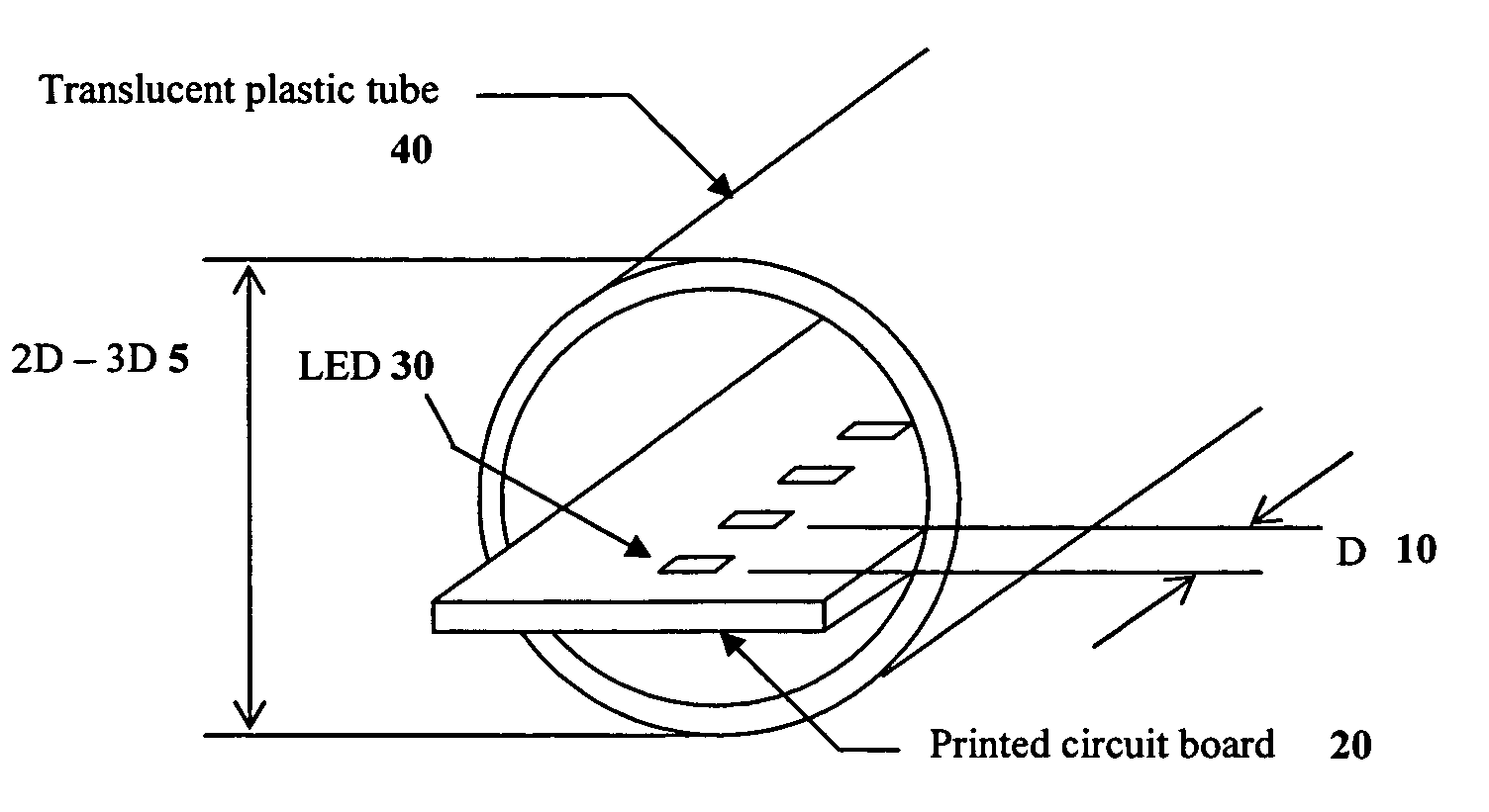
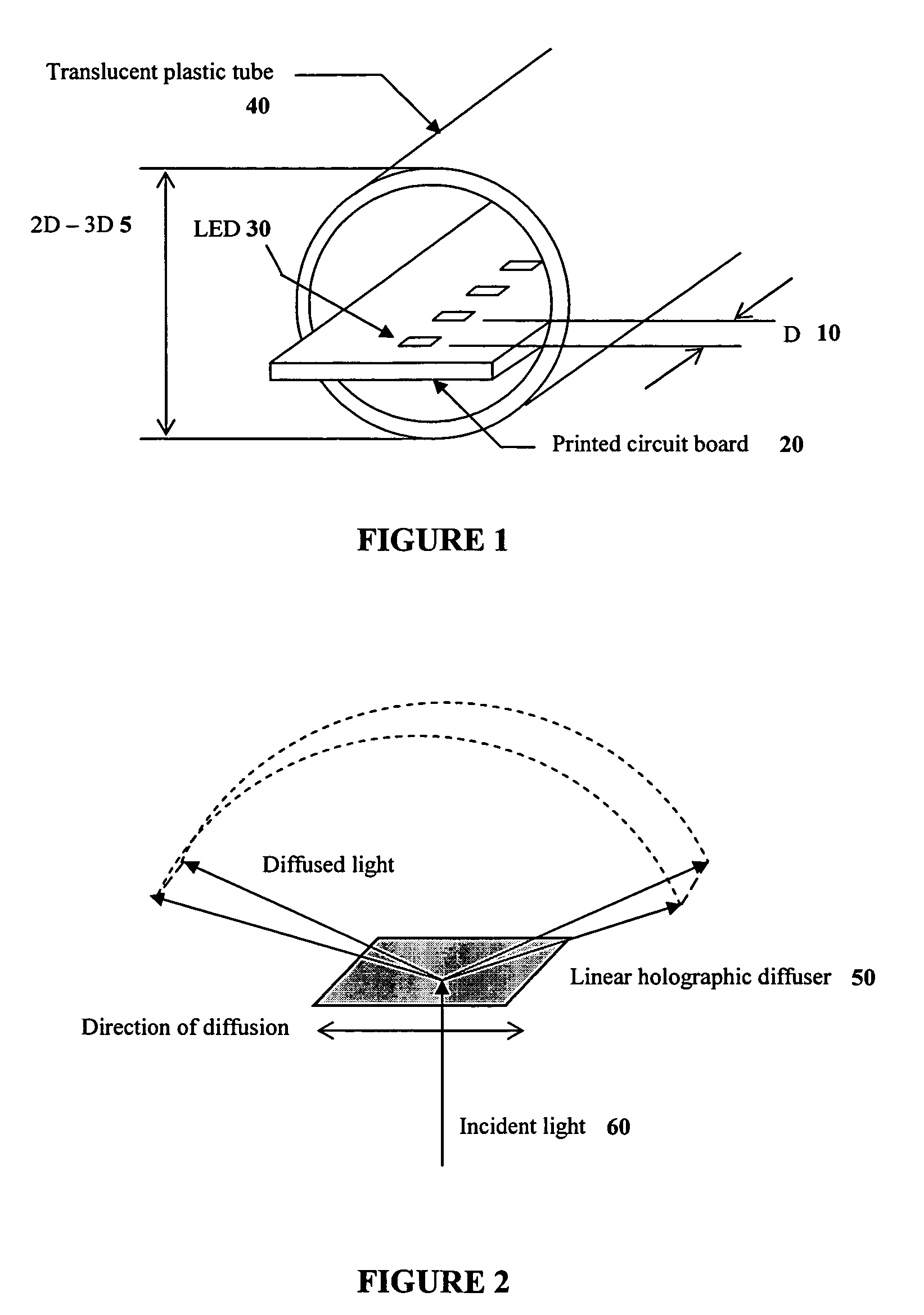
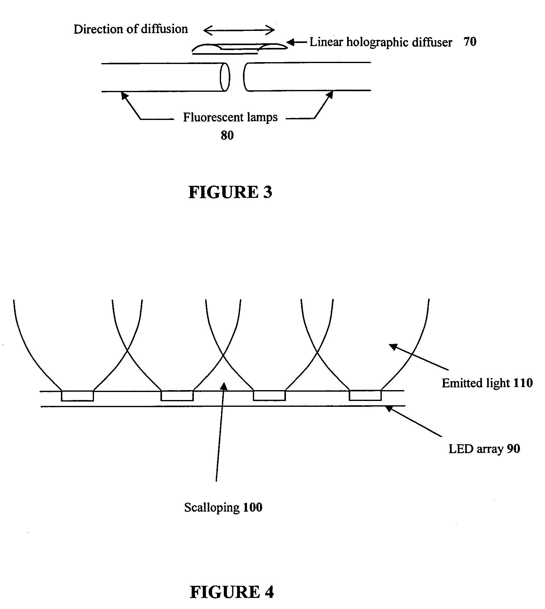
[0036]The term “light-emitting element” is used to define any device that emits radiation in the visible region of the electromagnetic spectrum when a potential difference is applied across it or a current is passed through it, for example, a semiconductor or organic light-emitting diode (LED) or other similar devices as would be readily understood, and may include any electronic circuit drivers that may be needed to control its activation. It would be readily understood by a worker skilled in the art, that a light-emitting element can emit radiation in the visible region of the electromagnetic spectrum or any other region for example in the infrared or ultraviolet regions.

[0037]The term “diffuser” is used to define a device that scatters incident electromagnetic radiation, including visible light, infrared and ultraviolet radiation by means of diffuse transmission or reflection into a variety of luminance distribution patterns.

[0038]Unless defined otherwise, all technica...


PUM


Abstract

The present invention provides a system and method for the diffusion of illumination from discrete light sources such that the illumination is blended and directed in one or more desired directions. The illumination system comprises a substrate having a plurality of light-emitting elements thereon which are arranged in an array, wherein these light-emitting elements produce illumination at one or more wavelengths. Proximate to the light-emitting elements is a diffuser, which collects the illumination produced by the discrete light-emitting elements and redirects this illumination in one or more predetermined directions, thereby blending together the one or more wavelengths of illumination and concentrating the illumination in the predetermined directions. The illumination system further comprises a power system, which provides energy to the light-emitting elements thereby resulting in their activation. Through the blending of the illumination produced by the discrete light-emitting elements together with the redirection of the illumination in a desired direction, both of which are enabled by the diffuser placed proximate to the discrete light-emitting elements, the creation of a blended pattern of illumination from these discrete light-emitting elements is provided, wherein this pattern of illumination can be one or more lines or planes of illumination.

Description

CLAIM OF PRIORITY[0001]This application claims priority from now expired U.S. Provisional Patent Application No. 60 / 489,172 filed Jul. 22, 2003.FIELD OF THE INVENTION[0002]The present invention pertains to the field of lighting and in particular to the area of light diffusion with respect to illumination generated by discrete light sources.BACKGROUND[0003]When using discrete light sources, for example light emitting diodes, to create an illumination effect, there is the need for the blending of the illumination created by these discrete light sources into a uniform lighting condition. For example, by fabricating a linear array of discrete light sources having a spacing therebetween, the light emitted thereby would typically be capable of creating neither a uniformly luminous linear line of light nor an even wash of light for wall washing or cove lighting, for example. In particular, problems arise when the illumination is being created by discrete light sources having a variety of c...

Claims


Application Information

Patent Timeline
Patent Type & Authority Patents(United States)
IPC IPC(8): F21V5/00F21S4/00F21V13/00G01J1/04G01J1/08G01J3/10G02B5/02
CPCF21S4/003F21V5/002G01J1/04G01J1/0474G01J1/08F21Y2101/02F21Y2113/00G01J3/10F21S4/20F21Y2115/10
Inventor ASHDOWN, IAN
Owner SIGNIFY HLDG BV
Why Eureka
Try Eureka