
Method And Apparatus For Generating 3D Images

a technology of 3d images and apparatus, applied in the field of apparatus for displaying 3d images, can solve the problems of unfavorable crosstalk, unfavorable image perception, uneven total intensity shown in fig. 7c,

Active Publication Date: 2008-08-28
BALOGH
View PDF12 Cites 122 Cited by
  • Summary
  • Abstract
  • Description
  • Claims
  • Application Information

AI Technical Summary

Benefits of technology

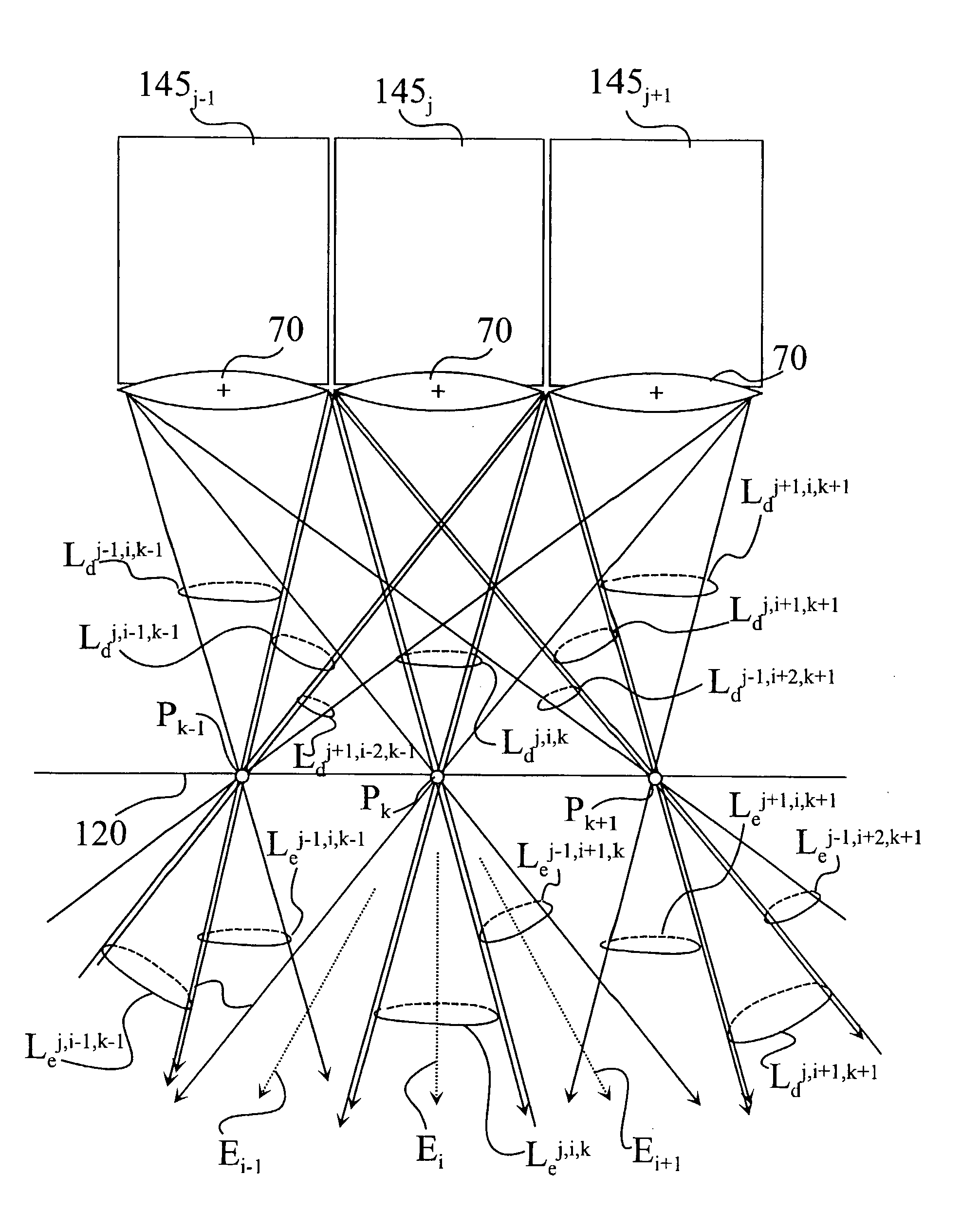
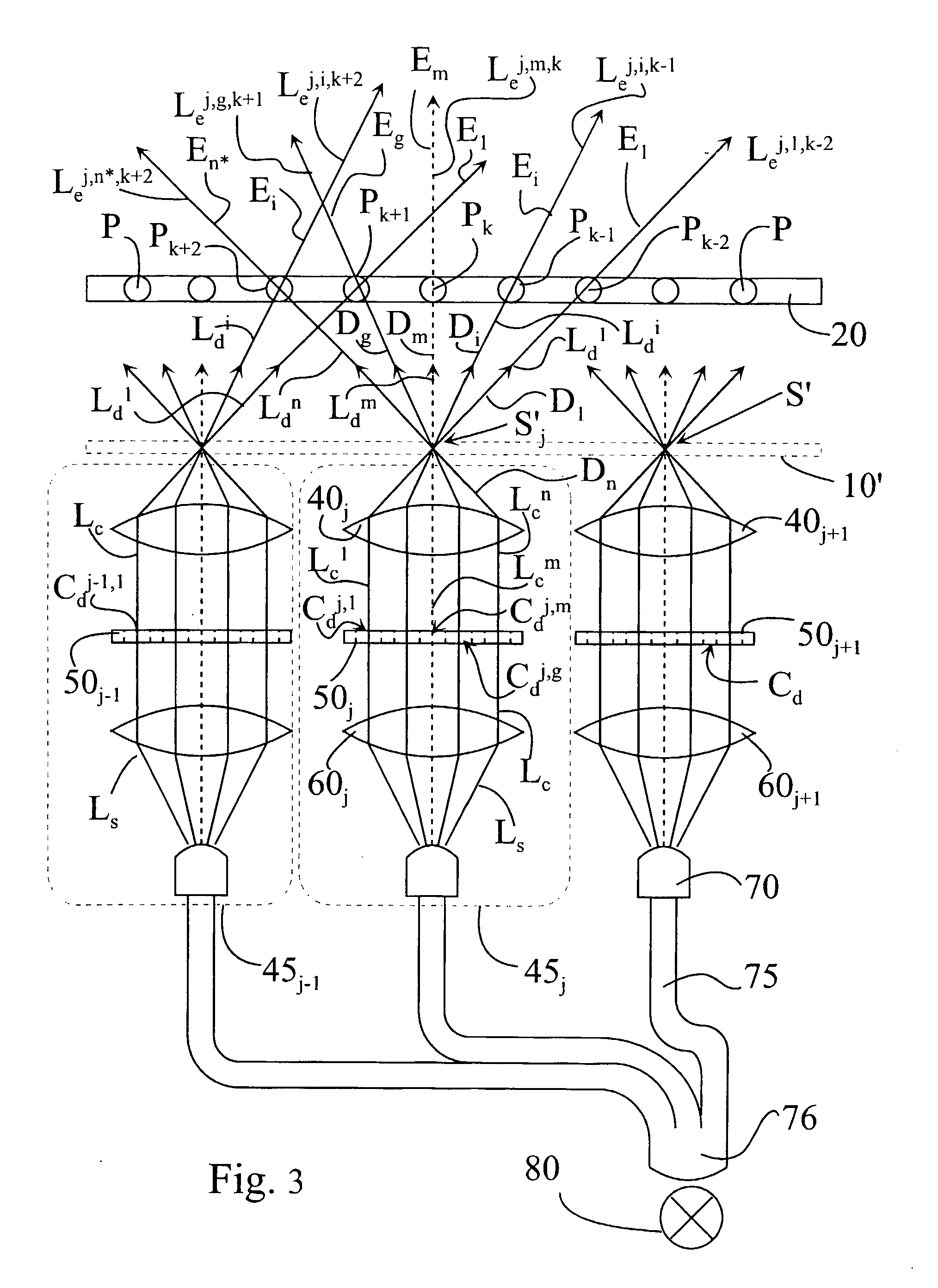
[0026]To avoid these obstacles and to allow building systems in practice that can display real three dimensional images with proper depth, the invention proposes an apparatus which directly generates the light beams with the proper divergence instead of using the screen alone for that purpose. The system comprises imaging means for generating the incident light beams with a convergent section converging substantially towards a point of the screen. It is proposed that a convergence of the incident light beams is substantially equal to the exit divergence of the light beams exiting the screen. A further advantage of the system is that the ideal intensity distribution character of the emitted light beams can be set precisely in combination of the intensity distribution of the convergent light beams generated by the modules and the screen diffusion characteristics.

Problems solved by technology

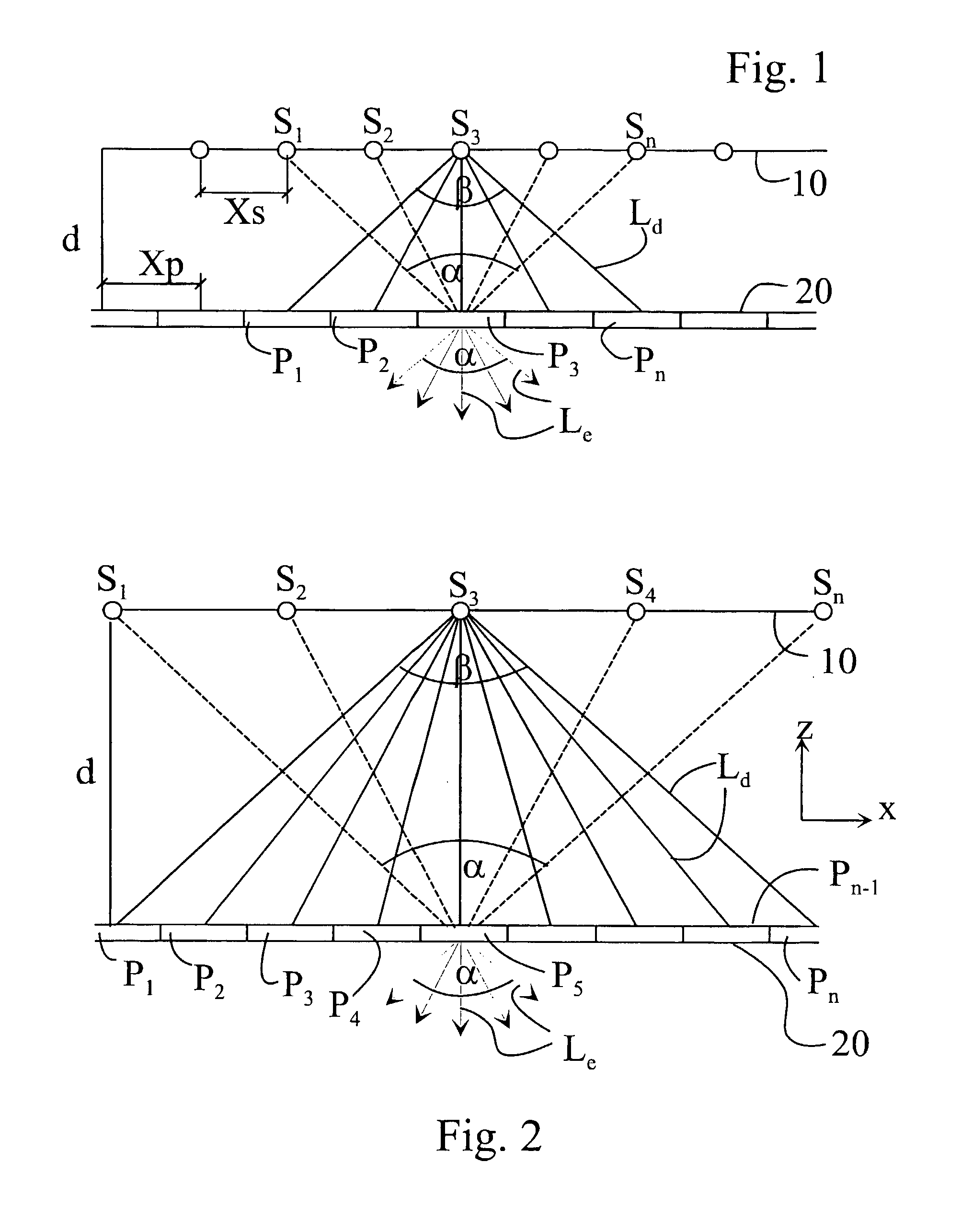
However, there is a problem with the approach where the necessary divergence δx of the emitted light beams Le is achieved with a diffusive screen, as shown for a single module 45 and a single deflected light beam Ld in FIG. 6A.
For the observer, it means that the perceived image will be blurred, the neighboring views will be simultaneously present in the three dimensional image and the apparatus is not capable of showing images with sharp contours.
The screen diffusion characteristic is a critical factor in such systems, and unfortunately, this Gaussian intensity distribution is inherent in all practical diffusers even in holographic diffusion screens.
The uneven total intensity shown in FIG. 7C or the undesirable crosstalk is practically unavoidable since these are conflicting requirements.
This strongly limits the performance of such systems and makes manufacturing high quality 3D displays impossible.
This is true for systems with achromatic holographic diffusion screens or if not holographic screens are used but other dispersing components, for example a lenticular lens system, it is difficult to realise the ideal diffusion characteristic (see FIGS. 6B, 7B) and serious alignment, colour dispersion problems arise, which again cause a deterioration of the perceived image.

Method used


Image

  • Method And Apparatus For Generating 3D Images
  • Method And Apparatus For Generating 3D Images
  • Method And Apparatus For Generating 3D Images

Examples


Embodiment Construction

[0089]As explained above, FIGS. 1 to 7 illustrate the principle of 3D generation disclosed in, among others, WO 01 / 88598. Here, the incident light beams Ld are substantially one-dimensional (collimated and thin) light beams, actually more rays than beams. These collimated light beams receive the appropriate divergence from the screen 20. The divergence angle δx largely corresponds to the angle γi between the incident light beams Ldi-Li+1. Here, the index x symbolises a divergence substantially in the horizontal direction, perceived when an observer looks perpendicularly at the screen 20. This is illustrated also in FIG. 8A. FIGS. 8A and 8B give a comparison of the prior art and the invention, when the observer looks at a display according to the prior art and the current invention, despite of the different way of generating the light beams and the different type of screens 20 and 120, he will theoretically observe the same exiting light beams, forming a 3D image.

[0090]Turning now to...


PUM


Abstract

The present invention is directed to an apparatus and method for displaying 3D images. The apparatus comprises: a) a screen with angular dependent diffusion characteristics for direction selectively forwarding light; b) a screen illuminating system, the screen illuminating system comprising multiple modules for generating multiple light beams incident on points of the screen, the modules being arranged so that each point of the screen is illuminated by multiple modules, and the incident light beams generated by one module are projected into multiple different directions from the module towards multiple different points of the screen, and further the different incident light beams generated by one module are forwarded towards different emitting directions from the screen, means for coding each incident light beam with the image information of a single image point in the module, where the 3D image perceived by an observer being generated by multiple modules; c) a control system to control the modules; and d) means for imparting an exit divergence to the exiting light beams being transmitted through or reflected from the screen, the measure of the exit divergence substantially corresponding to the angle between neighbouring emitting directions associated with the optically neighbouring modules, go as to provide a substantially continuous motion parallax in the 3D image perceived by an observer. The apparatus according to the invention comprises imaging means for generating the incident light beams with a convergent section converging substantially towards a point of the screen, where a convergence of the incident light beams is substantially equal to the exit divergence of the light beams exiting the screen. The modules can be video projectors, LED projectors, the optical engines of these, or the like, arranged periodically shifted, preferably in the horizontal direction and the diffuser screen is realised as a holographic screen, arrays of diffractive or refractive elements, retroreflective surfaces, or any combination thereof, for imparting a larger divergence to the exit light beams along at least one, preferably in the vertical direction, while in the other direction the angle of divergence provided by the screen is smaller than the angle between the neighbouring emitting directions associated with the optically neighbouring modules. The invention is also directed to a method implemented by the apparatus according to the invention.

Description

FIELD OF THE INVENTION[0001]The invention relates to an apparatus for displaying 3D images. The purpose of the invention is to improve known 3D generating apparatus, such as known from WO 01 / 88598.[0002]The invention particularly concerns such an apparatus which comprises a screen with angular dependent diffusion characteristics for direction selectively forwarding light, and a screen illuminating system. In the apparatus of the invention, the screen illuminating system comprises multiple modules for generating multiple light beams incident on points of the screen. The modules are arranged so that each point of the screen is illuminated by multiple modules, and the light beams generated by one module are projected into multiple different directions from the module towards multiple different points of the screen. The different light beams generated by one module, incident on the screen, are forwarded towards different emitting directions from the screen. The apparatus also comprises ...

Claims


Application Information

Patent Timeline
IPC IPC(8): G02B27/22G02B30/27H04N13/363
CPCG02B27/2214H04N13/0459H04N13/0425G02B30/27H04N13/327H04N13/363G02B30/00H04N13/00
Inventor BALOGH
Owner BALOGH
Learn More