
Hologram screen and a method of producing the same

a technology of hologram screen and hologram light, which is applied in the field of hologram screen and a method of producing the same, can solve the problems of difficult preparation of very large hologram screen, poor image quality, and inability to reproduce uniformly the color of image light on all areas of the hologram screen

Inactive Publication Date: 2001-11-29
DENSO CORP
View PDF0 Cites 6 Cited by
  • Summary
  • Abstract
  • Description
  • Claims
  • Application Information

AI Technical Summary

Benefits of technology

[0007] The second object of the present invention is to provide a method of producing a hologram screen in which an observer can observe a uniformly bright image without change of brightness and color to a broad extent on the hologram screen.
[0009] The fourth object of the present invention is to provide a hologram screen which has good transparency and no cloudy state so that the observer clearly and easily observe the back of the hologram screen.

Problems solved by technology

As representative problems to be solved in a conventional hologram screen, there are the quality of the image, such as unevenness of color and brightness on the hologram screen, cloudiness and a partial non-transparent state on the hologram screen, and the difficulty of preparing very large hologram screen.
That is, in the conventional art, it is impossible to reproduce uniformly the color of the image light on all areas of the hologram screen.
That is, there is a problem in which an unnatural image which gives large feeling of difference to the observer is reproduced in the conventional art.
When the color difference is larger than 0.1, unevenness of color may occur on the reproduced image.
As a result, the difference of the color on the hologram screen become large so that unevenness of color easily occurs in the reproduced image.
That is, the output light from the hologram screen is constituted by the light having more wide range of the wavelength so that the difference in the color becomes large and unevenness of color easily occurs in the reproduced image.
However, since the number of the interference fringe which can record is reduced in the case of the thin photosensitive material, the hologram screen having low effectivity is obtained.
If the .DELTA.T is larger than 0.5T.sub.0, the range of the thickness distribution of the hologram screen becomes too wide so that it may be very difficult to obtain the effect of reduction of unevenness of color.

Method used


Image

  • Hologram screen and a method of producing the same
  • Hologram screen and a method of producing the same
  • Hologram screen and a method of producing the same

Examples


first embodiment

[0410] (First Embodiment)

[0411] The first embodiment is explained in detail with reference to FIGS. 53 to 63. As shown in FIG. 56, the image light 331 from the image projector 22 is scattered and diffused on the hologram screen 31 so that it is possible to obtain the output light 332. As a result, the image is reproduced on the hologram screen 31. In this case, the half bandwidth of the hologram spectrum is 100 nm or more on the hologram screen (see FIG. 61).

[0412] As shown in FIGS. 53 to 55, the hologram screen 31 is formed by the hologram element which is prepared by the interference fringe. That is, the diffusion light passing through the light diffusion body 3116 having the large light diffusion angle is used as the object light 3117, and the non-diffusion light is used as the reference light 3118. The object light 3117 and the reference light 3118 are irradiated onto the photosensitive material 3120 in order to form the interference fringe.

[0413] As shown in FIG. 56, the displa...

third embodiment

[0440] (Third Embodiment)

[0441] In the third embodiment, the intensity ratio R / O of the reference light (R) and the object light (O) is set to 0.1 to 30, and the reference light and the object light are irradiated on the photosensitive material in order to form the interference fringe on the hologram element. In this case, the half bandwidth of the hologram spectrum is 100 nm or more. The light diffusion body is formed by laminating four double-faced ground glasses. The intensity ratio R / O of the reference light and the object light is 3, and the incident angle .theta.r and the incident angle .theta.e are 30.degree.. As shown in FIG. 66, when the intensity ratio R / O is in the range of 0.1 to 30, the half bandwidth is 100 nm or more. It is obvious that the hologram element has the good color reappearance of the image.

fourth embodiment

[0442] (Fourth Embodiment)

[0443] In this embodiment, the peak wavelength of the hologram spectrum is either 525 nm or less, or 585 nm or more. The thickness of the photosensitive material (for example, the photopolymer made by Dupont Co.) is 6 .mu.m. The light diffusion body is formed by laminating three double-faced ground glasses, and the intensity ratio R / O of the reference light and the object light is 0.8, 3 and 5. Further, the incident angle .theta.r and the incident angle .theta.e are 30.degree..

[0444] As shown in FIG. 67, as well as the first embodiment, the intensity ratio R / O becomes large, the peak wavelength of the hologram is shifted to the short wavelength side. Further, the peak wavelength of the hologram spectrum is either 525 nm or less, or 585 nm or more. When the half bandwidth is 100 nm or more, particularly, when it is 140 nm or more, it is not necessary that the peak wavelength is 525 nm or less, or 585 nm or more. When the peak wavelength is either 525 nm or l...


PUM


Abstract

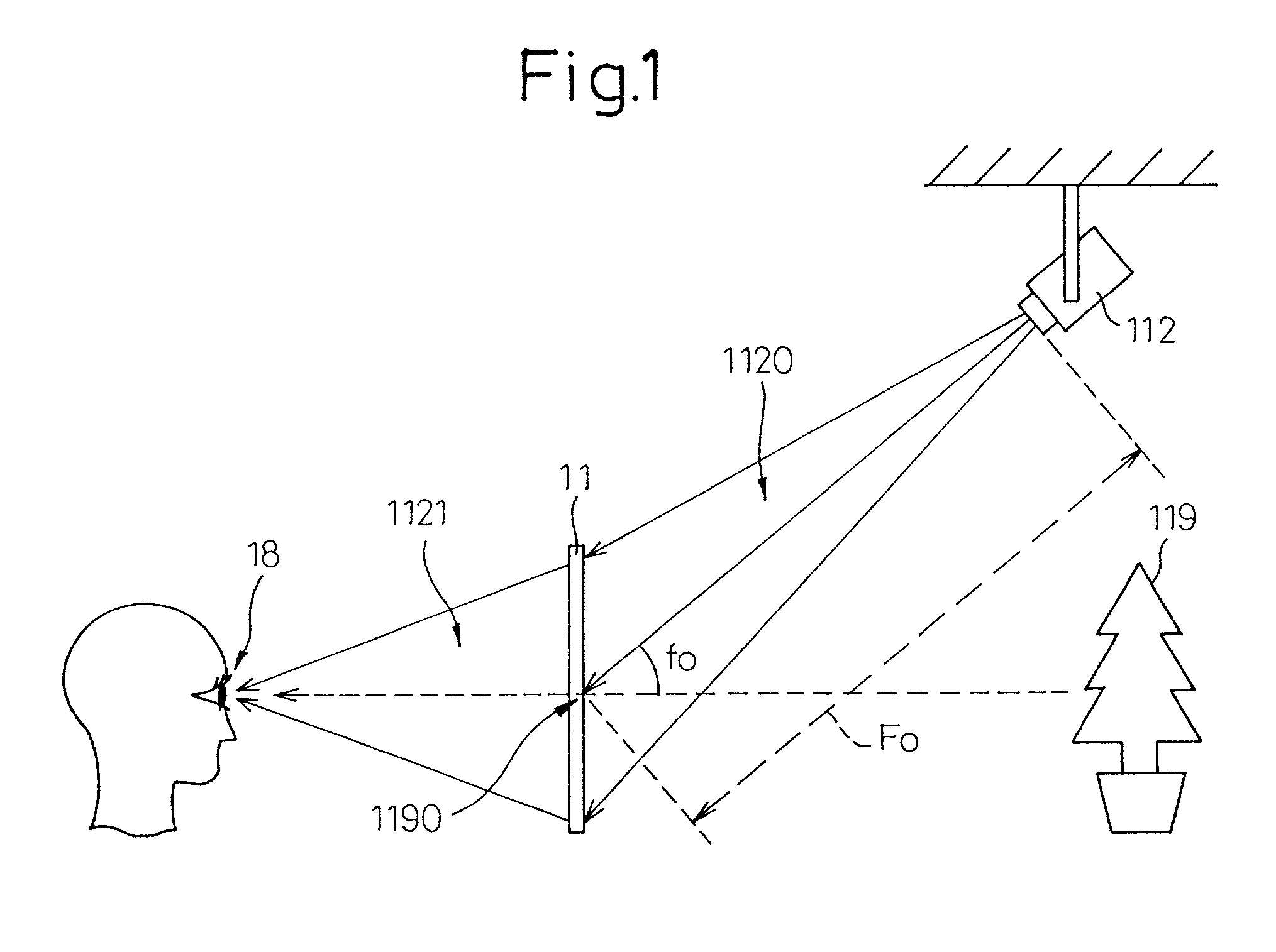
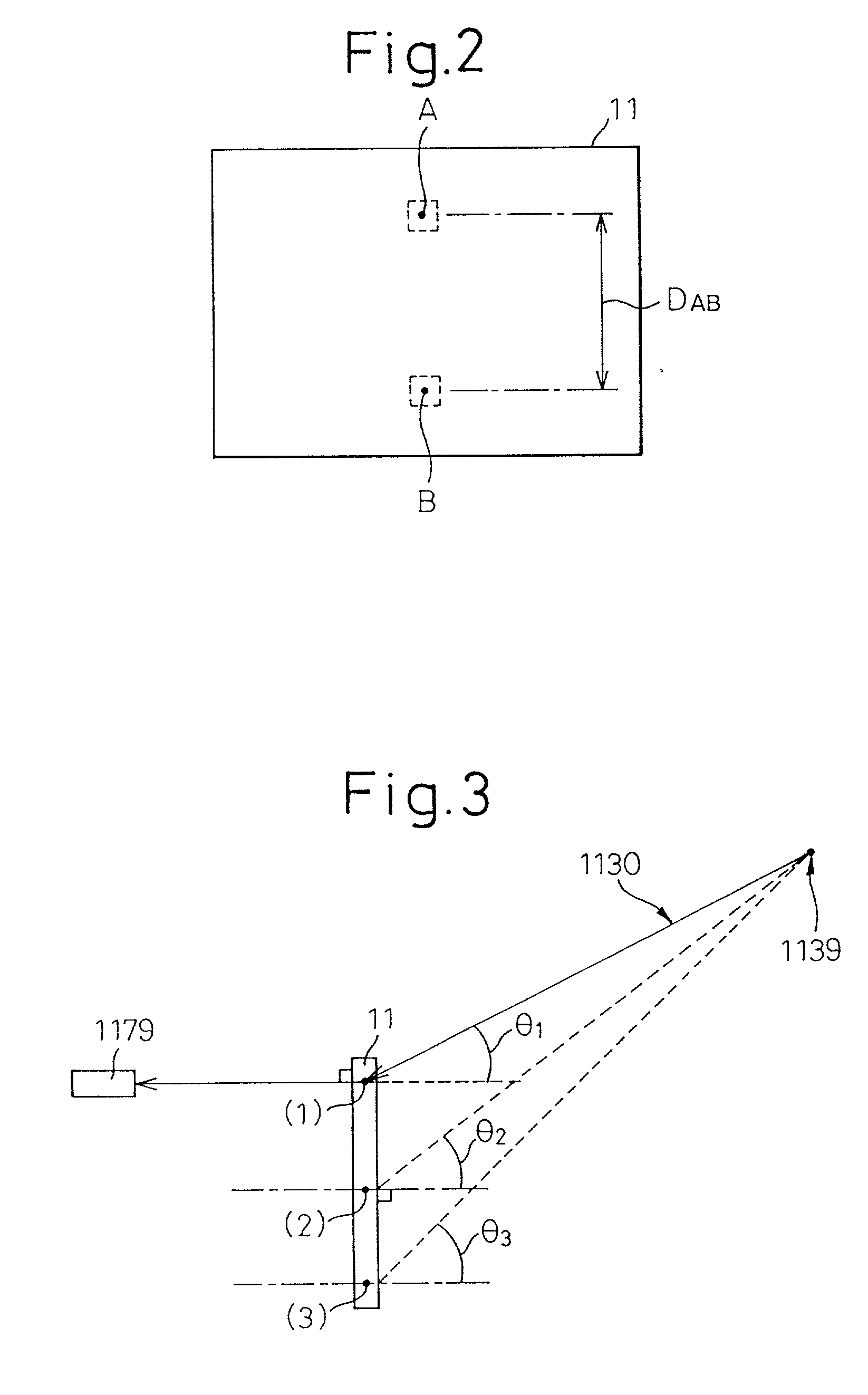
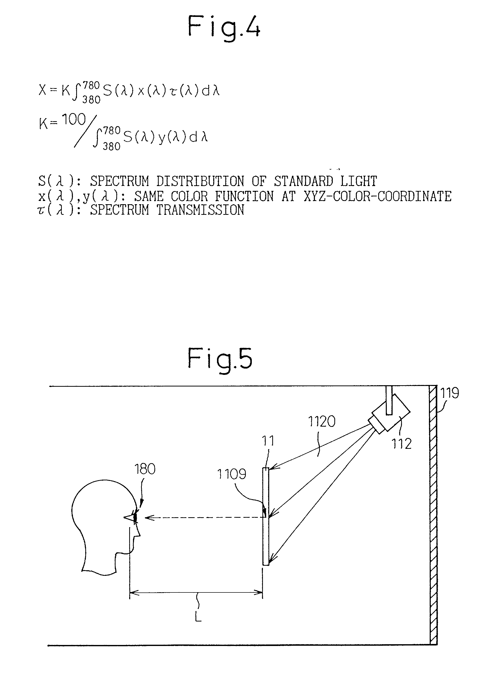
In a hologram screen for reproducing an image based on an output light obtained by scattering and diffusing an image light from an image projector, when a white light (image light) is projected on the hologram screen; and when a distance between two points at optional two points A and B on a surface of the hologram screen is given by 20 cm or less, and a value of the CIE 1976 chromaticity coordinate (u', v') at the point A is given by (u'A, v'A) and the value of the CIE 1976 chromaticity coordinate (u', v') at the point B is given by (u'B, V'B); the output light perpendicularly from the surface of the hologram screen has a color distribution in which a color difference DELTAu'v' between two points A and B is derived from the following formula (1) and given by 0.06 or less, where, the formula (1) is expressed by,<paragraph lvl="0"><in-line-formula>DELTAu'v'=[(u'A-u'B)2+(v'A-v'B)2]½ (1)< / in-line-formula>Further, the output light, which is output to a viewpoint defined by the following formula (2) from the surface of the hologram screen, has the color distribution in which a color difference DELTAu'v' between two points A and B is derived from the above formula (1) and given by 0.01 or less, where, the formula (2) is expressed by,<paragraph lvl="0"><in-line-formula>H / 2L=0.1 (2)< / in-line-formula>in the formula (2), L is a distance between the viewpoint and a center of the hologram screen, and H is a length of the hologram screen in the direction of the height.

Description

[0001] 1. Field of the Invention[0002] The present invention relates to a hologram screen and a method of producing the same. In particular, a first aspect of the present invention relates to a hologram screen for reproducing an image based on an output light obtained by scattering and diffusing an image light which is input from an image projector, and a producing method of the same; a second aspect of the present invention relates to a producing method of a hologram element which can be used as a display apparatus for displaying the image, such as a still image and an animation, by irradiating the image light thereto; a third aspect of the present invention relates to a hologram screen and a producing method of the same; and a fourth aspect of the present invention relates to a hologram screen for reproducing an image based on an output light obtained by scattering and diffusing an image light.[0003] 2. Description of the Related Art[0004] A hologram screen, which is formed by a h...

Claims


Application Information

Patent Timeline
IPC IPC(8): G02B5/32G02B27/00G02B27/01
CPCG02B5/32G02B27/0103G02B2027/0118
Inventor TAKADA, KENICHIRO
Owner DENSO CORP
Learn More