Flexible spark plug

a flexible, spark plug technology, applied in the direction of spark plugs, basic electric elements, electric devices, etc., can solve the problems of difficult installation, removal and servicing of spark plugs, severe space around spark plugs, and none of these solutions are completely satisfactory, so as to achieve the same conductivity and diameter, less vertical clearance, and convenient access

Inactive Publication Date: 2011-11-22
BISHOP BOBBY GLEN
View PDF10 Cites 2 Cited by
  • Summary
  • Abstract
  • Description
  • Claims
  • Application Information

AI Technical Summary

Benefits of technology

[0006]The flexible spark plug embodiments of the present invention presented herein solve the problem of accommodating a spark plug in an engine compartment where access to the spark plug is limited. The flexible spark plug employs a ceramic insulator with a shortened length above the spark plug's hexagonal nut at the terminal end of the plug as compared to a standard spark plug. It uses a flexible conductive wire instead of a central electrode rod. The flexible conductive wire has the same conductivity and diameter as a central electrode rod, and is covered by an insulating flexible covering. When installing an embodiment, the flexible electrode may be bent away from the axis of the ceramic insulator. This novel design allows the spark plug to be installed in the engine block in a way that provides less vertical clearance than required for a standard plug, and allows the spark plug terminal to be attached to the ignition wire clip in a location that is easier to access.

Problems solved by technology

In some cases, space around the spark plug is severely limited.
Therefore, installation, removal and servicing of the spark plug can be difficult.
However none of these solutions are totally satisfactory.

Method used


Image

  • Flexible spark plug
  • Flexible spark plug
  • Flexible spark plug

Examples


Embodiment Construction

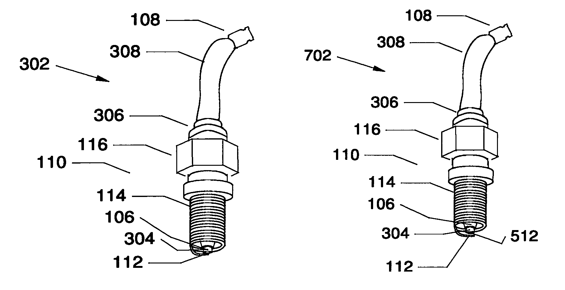
[0021]In the following, the terms top, upper, bottom and lower are interpreted as viewed in the figures. A spark plug has a terminal end, where a clip from in ignition wire is attached, and an ignition end where a spark is generated.

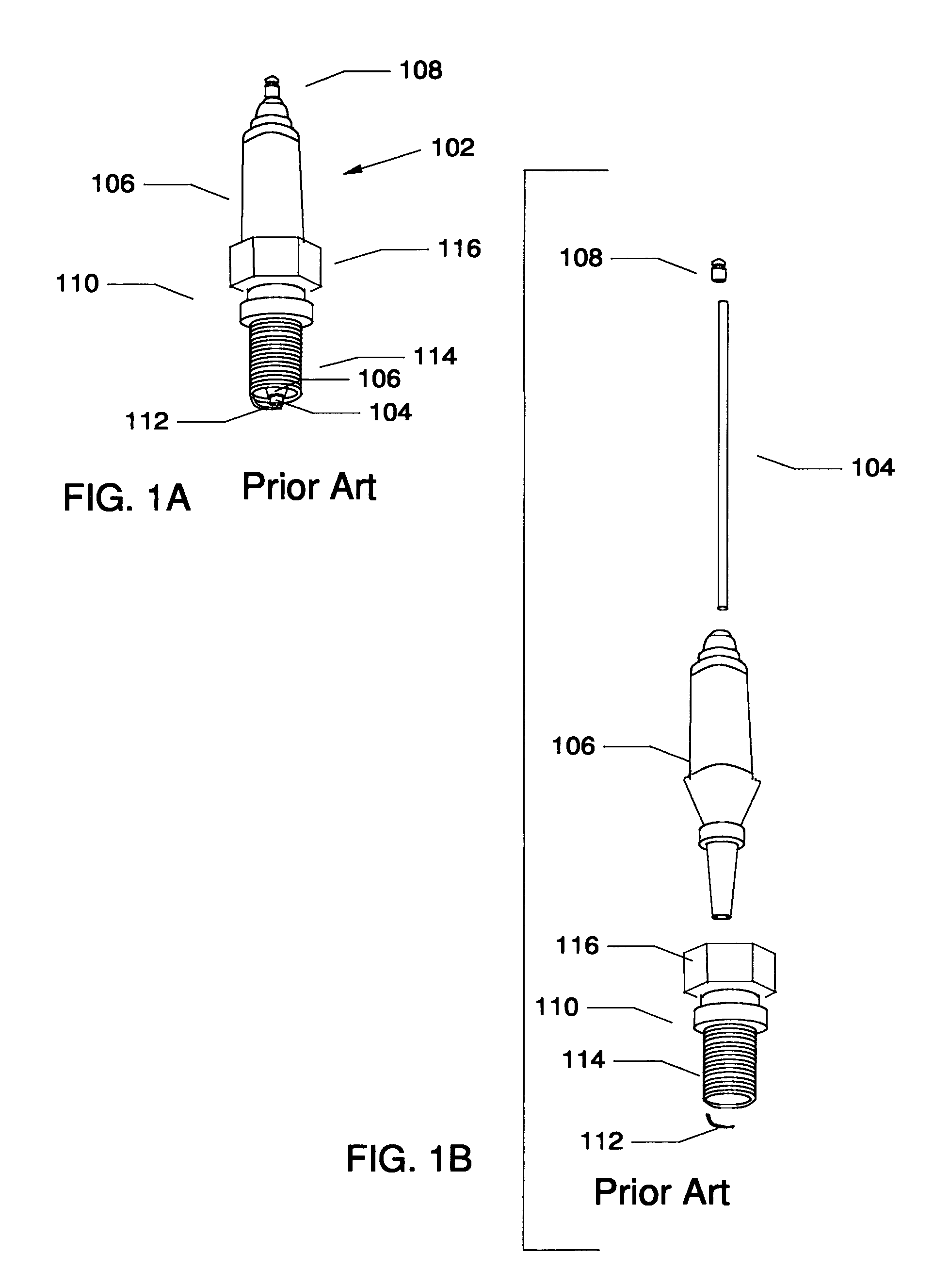
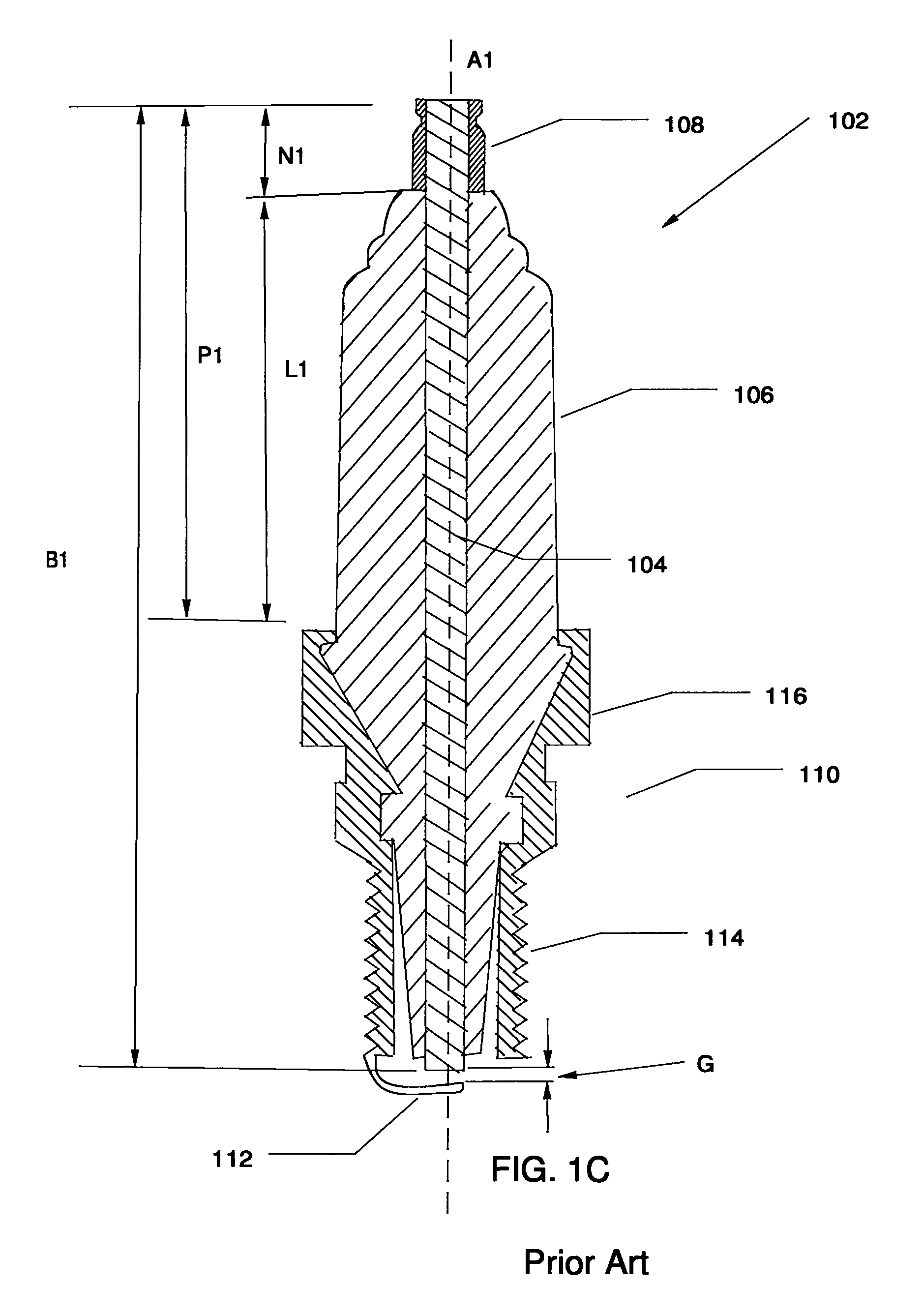
[0022]FIG. 1A illustrates a perspective view of a first prior art spark plug 102. FIG. 1B illustrates an exploded view of first prior art spark plug 102. FIG. 1C is a sectional view of first prior art spark plug 102 along a central axis A1. Referring to FIGS. 1A, 1B, and 1C, first prior art spark plug 102 has a rod-like central electrode 104 of length B1, a hollow cylindrical ceramic insulator 106 encasing central electrode 104, a conductive terminal 108 having length N1 attached to central electrode 104 at the top end, a hollow cylindrical metal shell 110 partially encasing ceramic insulator 106, and an L-shaped ground electrode 112 attached to the bottom of metal shell 110. The spark plug components are disposed along a central axis A1.

[0023]Central el...


PUM


Abstract

A spark plug designed for fitting in tight spaces of an engine compartment is disclosed. The spark plug has a conductive terminal attached to one end of a flexible central electrode and has a ceramic insulator partially encasing the flexible central electrode. The part of the flexible central electrode between the ceramic insulator and the conductive terminal is encased in a flexible insulator. The flexible part of the central electrode may be bent away from the axis of the ceramic insulator accommodating both installation and servicing of the spark plug in tight spaces.

Description

CROSS-REFERENCE TO RELATED APPLICATIONS[0001]This application claims the benefit of the U.S. Provisional Patent Application No. 61 / 209,048 filed Mar. 3, 2009 by the present inventor. This provisional patent application is incorporated herein by reference.TECHNICAL FIELD[0002]The present invention relates to spark plugs, more particularly to spark plugs that are used in small cramped spaces.BACKGROUND OF THE DISCLOSURE[0003]A spark plug for an internal combustion engine generally is comprised of a rod-like central electrode, a hollow cylindrical ceramic insulator encasing the central electrode, a conductive terminal attached to the central electrode at the spark plug terminal end, a hollow cylindrical metal shell partially encasing the ceramic insulator having threads for mating the spark plug with the engine block, a hexagonal nut for gripping the plug with a wrench, and an L-shaped ground electrode attached to the ignition end of the metal shell.[0004]When the spark plug is install...

Claims


Application Information

Patent Timeline
Patent Type & Authority Patents(United States)
IPC IPC(8): H01T13/20
CPCH01T13/20
Inventor BISHOP, BOBBY GLEN
Owner BISHOP BOBBY GLEN
Why Eureka
Try Eureka