Method of concurrent multipath transfer based on relational paths

a multipath transfer and relational path technology, applied in the field of computer network, can solve the problems of failure of the upper layer of the other packet to be handed in, mutual restriction among multiple paths, and out of order received tsn in the receiver

Inactive Publication Date: 2011-11-29
BEIJING JIAOTONG UNIV
View PDF5 Cites 2 Cited by
  • Summary
  • Abstract
  • Description
  • Claims
  • Application Information

AI Technical Summary

Benefits of technology

[0007]The purpose of this invention is to provide a method of CMT based on the relational paths, in which lost packets and abnormal paths can be found as fast as possible, and it will retransmit the lost packets quickly, so as to avoid all paths from failing to hand in packets to upper layer only for the abnormity in one path, which limits the speed of whole association.
[0009]When using CMT, because the receiver buffer is unique, the lost packet must be found as soon as possible for retransmission, to avoid all paths from failing to hand in packets to upper layer only for the abnormity in one path, which causes the blocking of receiver's head-of-line blocking and limits the speed of whole association.
[0010]Allowing pointing out the lost packet among paths can make a lost packet to be found as soon as possible. The improved mechanism of fast retransmit can decrease the number of unnecessary fast retransmit. The equivalent mechanism between fast retransmit and timeout retransmit can solve the problem that the improved fast retransmits may be done instead of timeout retransmit.

Problems solved by technology

Because of global superiority of the Transmission Sequence Number (TSN), when multiple paths are used to transmit packets at the same time, the difference of transmission delay among each path will generate the problem that the received TSN is out of order in the receiver.
When packets are handed in, it will cause mutual restriction among multiple paths.
The problem of SFR algorithm is that the algorithm makes the transmissions among paths independently, but the buffer in the receiver is still exclusive.
Any lost packet will cause failure in handing in upper layer of other packets after the lost packet.
So, only to make path transmission relatively independent during the transmission cannot make all paths to work as a single path transmission.

Method used


Image

  • Method of concurrent multipath transfer based on relational paths
  • Method of concurrent multipath transfer based on relational paths
  • Method of concurrent multipath transfer based on relational paths

Examples


Embodiment Construction

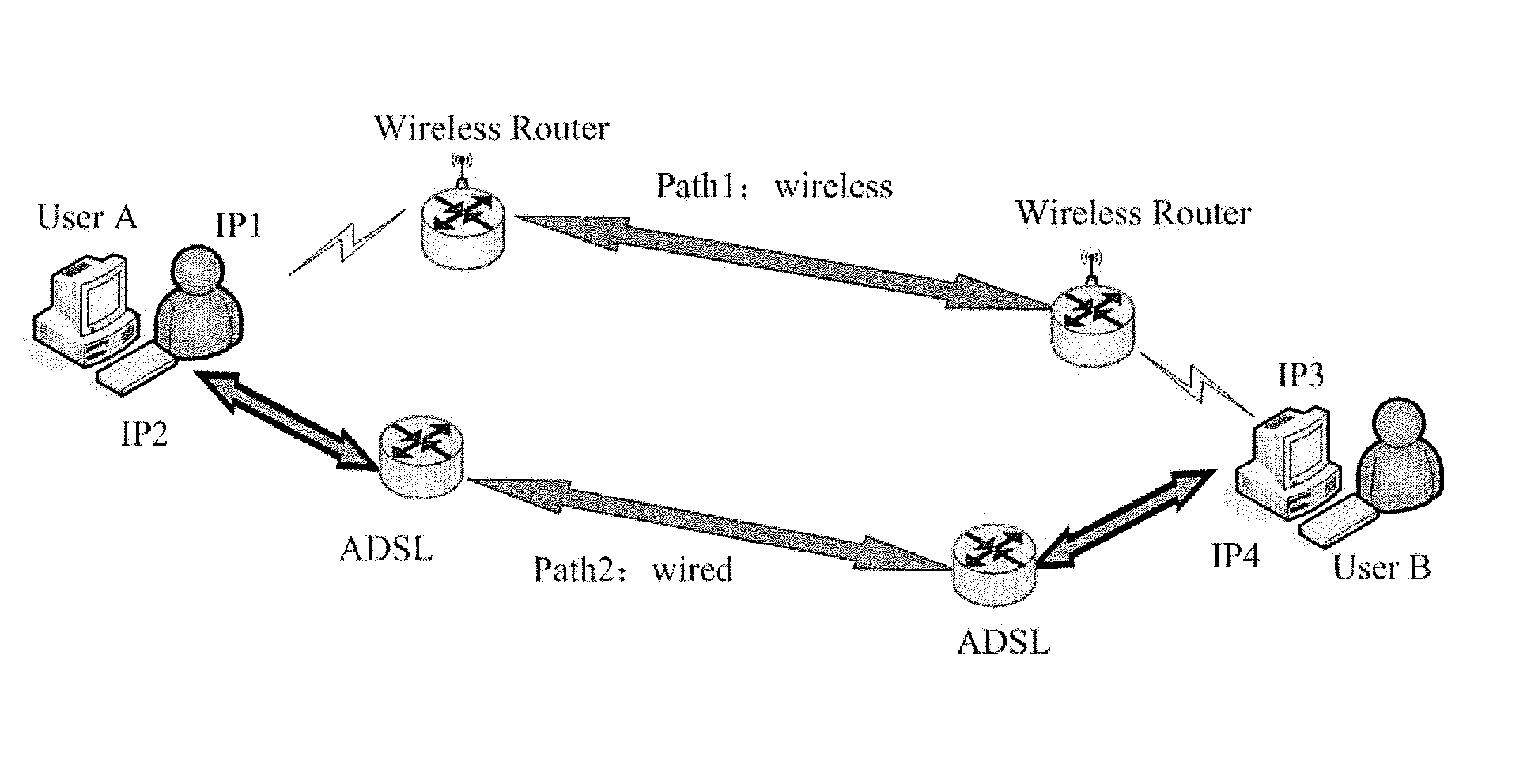
[0015]According to this invention, for the problem of packets disorder between paths, paths are allowed to point out lost packet mutually and generate one or more gap reports.

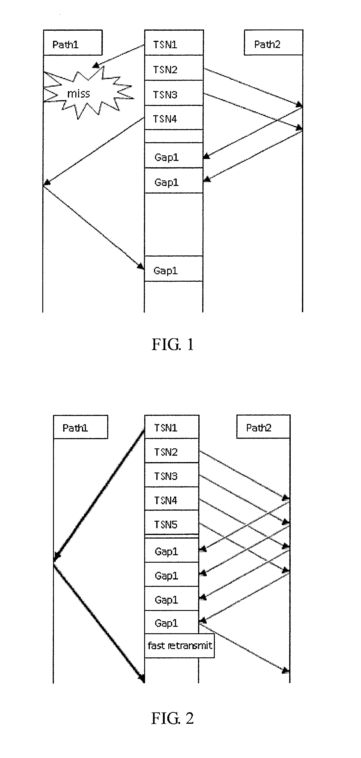
[0016]For example, in FIG. 1, TSN1 is lost in path1, TSN2 and TSN3, which are sent in path2, can also point out TSN1 is a lost packet though a gap report.

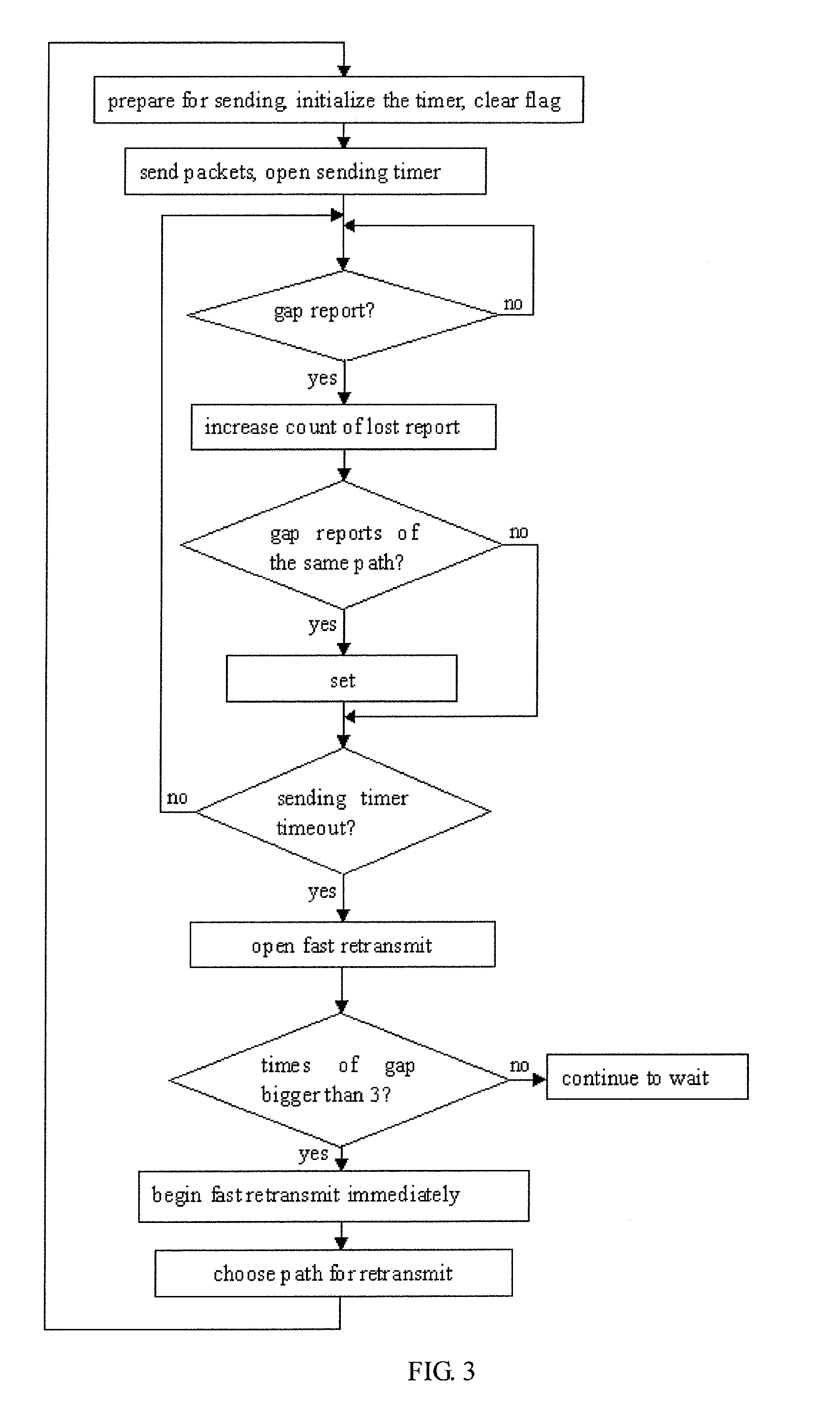
[0017]It is one of embodiments that when receiving a Selective Acknowledgement (SACK) with one gap report, it is to:[0018](1) find out the lost TSN number Tm which is pointed out by the gap report; and[0019](2) increase the lost report counter of Tm.

[0020]After allowing paths to point out lost packets mutually, there will be plenty of gap reports because of the performance difference between paths. But many of the gap reports are caused by the temporary packet lacking resulted from the different delay between paths, instead of losing.

[0021]When the difference between path delays is large enough, it may lead to unnecessary fast retransmit. FIG. 2 is an example ...


PUM


Abstract

A method of Concurrent Multipath Transfer which is based on the relational paths, characterized in that for a packet lost in a path, it allows other packets sent from the path and / or other paths to point out the lost packet through a gap report. According to the present invention, any lost packets and abnormal paths can be found as fast as possible, and can be retransmitted quickly. So this method can avoid the failure of all paths from handing in packets to upper layer only for the abnormity in one path, which limits the speed of whole association.

Description

TECHNICAL FIELD[0001]This invention relates to a method of Concurrent Multipath Transfer (CMT) based on relational paths, which belongs to the Technical Field of Computer Network.PRIOR ART[0002]Because of global superiority of the Transmission Sequence Number (TSN), when multiple paths are used to transmit packets at the same time, the difference of transmission delay among each path will generate the problem that the received TSN is out of order in the receiver. When packets are handed in, it will cause mutual restriction among multiple paths.[0003]Aiming at the disorder problem of packets among multiple paths, most existing implementation scheme of CMT use Split Fast Retransmit (SFR) to resolve it.[0004]The core of SFR algorithm is that only when the packets are sent in the same path, can it point out the lost packet and increase the lost gap counter.[0005]The problem of SFR algorithm is that the algorithm makes the transmissions among paths independently, but the buffer in the re...

Claims


Application Information

Patent Timeline
Patent Type & Authority Patents(United States)
IPC IPC(8): H04L1/00H04L12/26H04L12/28H04J3/26H04L12/56
CPCH04L1/1809H04L1/1841H04L1/188H04L1/22H04L2001/0096
Inventor ZHANG, HONGKELIU, CHANGYANG, DONGDONG, PINGQIN, YAJUANYAN, HUANSUN, LIANG
Owner BEIJING JIAOTONG UNIV
Why Eureka
Try Eureka