Methods and devices for partial upper layer frame loss detection based retransmission

a technology of retransmission and loss detection, applied in data switching networks, frequency-division multiplexes, instruments, etc., can solve problems such as transmission failures, delay performance, transmission failures, etc., to prevent both wire line and wireless communication networks from achieving ideal throughput and delay performance, and reduce the likelihood of memory unit overflow

Active Publication Date: 2007-07-03
RPX CORP +1
View PDF9 Cites 4 Cited by
  • Summary
  • Abstract
  • Description
  • Claims
  • Application Information

AI Technical Summary

Benefits of technology

[0023]Accordingly, the present invention envisions techniques for detecting the partial loss of an upper layer frame. A detection platform determines whether a received packet is a final packet in a particular upper layer frame. A comparator platform is then adapted to compare variables indicative of whether all packets in the particular upper layer frame have been received correctly when a final packet is detected. Finally, a transmission platform is adapted to send a signal indicative of whether a correct version of the particular upper layer frame was received so lost packets can be retransmitted quickly.

Problems solved by technology

Several factors prevent both wire line and wireless communication networks from achieving ideal throughput and delay performance.
Principally among them are transmission failures caused by interference, weak transmissions or faulty reception.
This reduces the likelihood that the memory unit will overflow.
On the other hand, frequent acknowledgements consume the bandwidth of a reverse link, degrade the throughput and delay performance of the reverse link and interfere with other transmissions.
For these and a variety of reasons, current acknowledgement techniques are inefficient.
While, as discussed above, existing acknowledgement techniques generally facilitate faster communications, these techniques must also be utilized efficiently or their benefit to a system's performance will be lost.
Therefore, it is unacceptable to allow an uncontrolled volume of acknowledgement signals to be sent to a transmission node.

Method used


Image

  • Methods and devices for partial upper layer frame loss detection based retransmission
  • Methods and devices for partial upper layer frame loss detection based retransmission
  • Methods and devices for partial upper layer frame loss detection based retransmission

Examples


Embodiment Construction

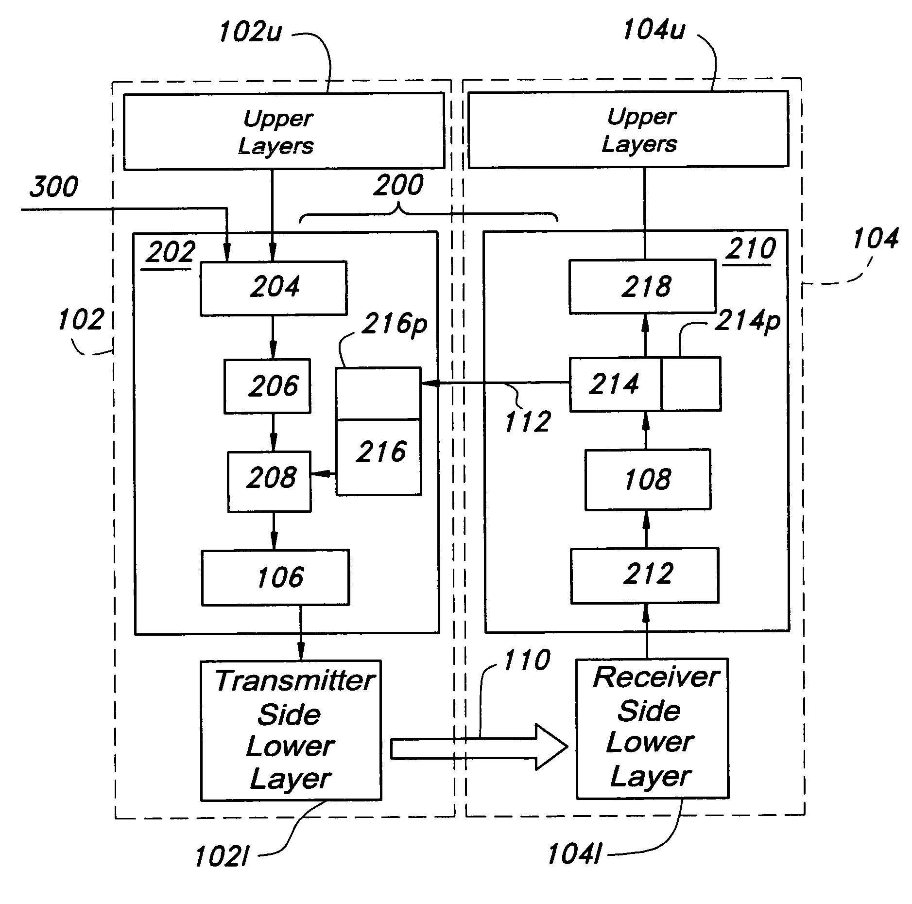
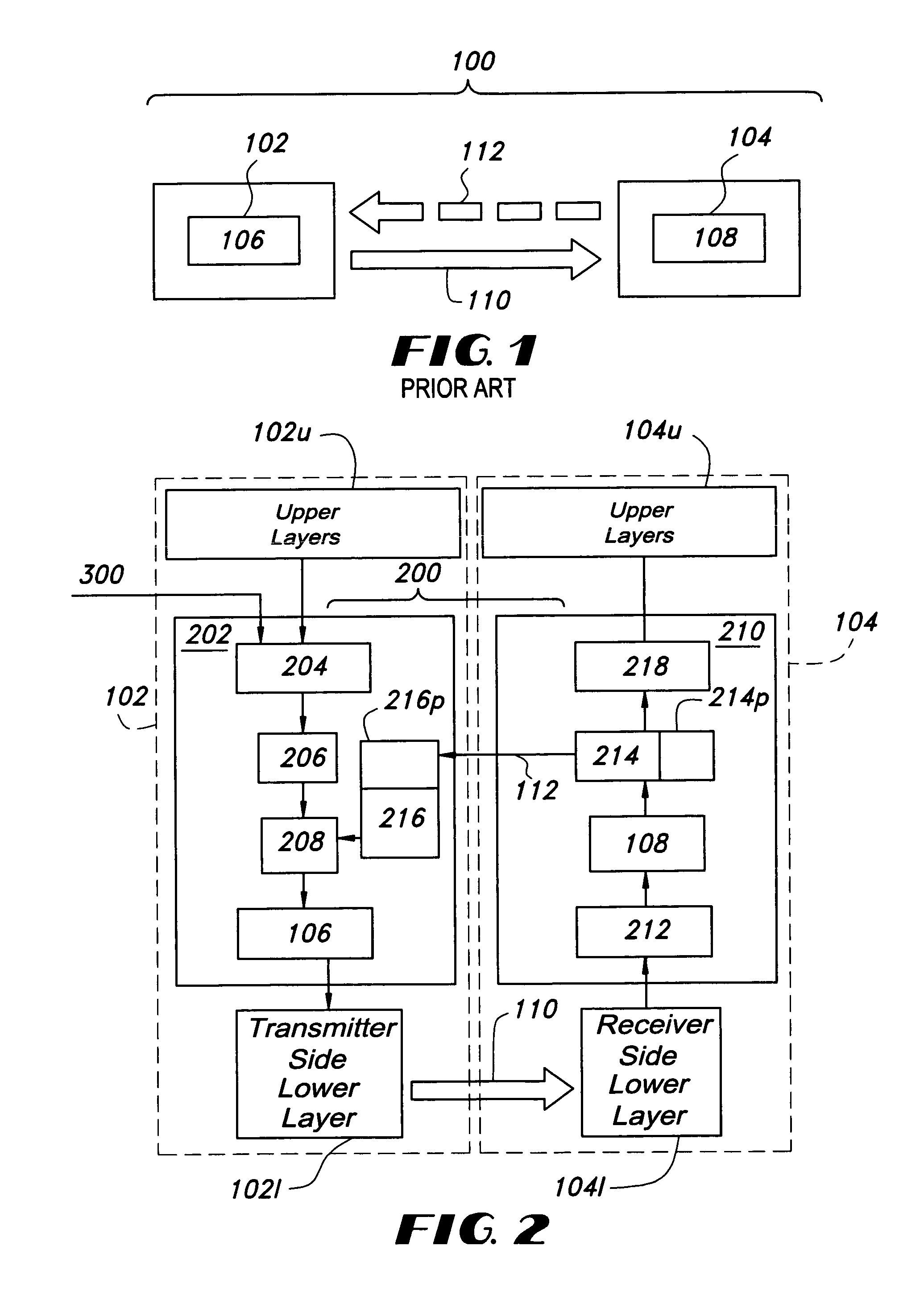
[0029]Those skilled in the art should note that while certain elements of the following invention are referred to as transmission or reception nodes, the functions of these elements can be carried out by the same program, module or device, such as a transceiver. The nomenclature in the discussion above and below is used merely to present features and functions of the invention in a clearer form, rather than to limit any particular program, module or device that may be utilized to implement these features and functions.

[0030]One embodiment of the present invention is implemented within a 3G communication network. However, the present invention is robust enough to be applied to any communication network that utilizes retransmission. The protocol stack for a preferred 3G communication protocol consists of a few layers, among them the RLC layer, a lower layer and a MAC layer. The present invention envisions the retransmission of packets from the RLC layer. In one embodiment of the prese...


PUM


Abstract

The present invention is aimed at techniques for detecting the “partial loss” of an upper layer frame. One technique envisions a detection platform adapted to determine whether a packet is a final packet for a particular upper layer frame. A comparator platform then compares packets received free of transmission errors with variables indicative of whether all received packets in the particular upper layer frame have been received correctly when a final packet is detected. A transmission platform then sends a signal indicative of whether the packets received without transmission errors constitute the particular upper layer frame so that lost packets can be retransmitted quickly.

Description

FIELD OF THE INVENTION[0001]This invention relates to the fields of wireless and wire line communication networks and, more specifically, to methods and devices for the detection of the partial loss of an upper layer frame.BACKGROUND OF THE INVENTION[0002]A common function of a data communication system is to successfully send data “packets” containing desired information from a transmission point or node to a reception point or node. Before going further, it should be understood that the term “node” may indicate one or more hardware, software or firmware elements which may be combined or used separately to carry out transmission and / or reception of packets, etc. . . . In order for such a system to perform efficiently, bits of information are grouped together to form an “upper layer frame”. Upper layer frames are then further subdivided or concatenated into packets, the basic units used for transmission in a communication network.[0003]A communication network's efficiency is measure...

Claims


Application Information

Patent Timeline
Patent Type & Authority Patents(United States)
IPC IPC(8): H04J1/16H04B7/216H04J3/24H04L1/14H04L12/28H04L12/66H04Q7/00H04L1/00H04L1/16H04L1/18H04L29/08
CPCH04L1/0083H04L1/1809H04L1/1685H04L1/1848H04L69/32H04L69/321
Inventor SU, HSUAN-JUNGZHANG, QINQING
Owner RPX CORP
Why Eureka
Try Eureka