Inkjet printing apparatus and inkjet printing method

a technology of inkjet printing and printing apparatus, which is applied in the direction of printing mechanism, spacing mechanism, printing, etc., can solve the problems of density unevenness (time interval unevenness), low printing efficiency, and low printing efficiency, and achieve the effect of density unevenness

Active Publication Date: 2011-12-06
CANON KK
View PDF22 Cites 3 Cited by
  • Summary
  • Abstract
  • Description
  • Claims
  • Application Information

AI Technical Summary

Benefits of technology

An object of the present invention is to provide an inkjet printing apparatus and an inkjet printing method that enable density unevenness, due to a difference in printing time intervals according to scans in bidirectional printing, to be resolved without causing changes in printing operation as much as possible.
Consequently, high image quality printing, without differences of density unevenness between unit areas, can be performed, and together with bidirectional printing, high speed printing and high image quality printing can be achieved at the same time.
With the second aspect of the present invention, in the multi-scan printing that completes the printing of each unit area by the plurality of scans of the print head, in which the forward scan and the backward scan are alternated, the maximum ink applying amounts differ according to the printing time intervals between the plurality of scans, which intervals in turn differ according to the positions in the scan direction of each unit area. The density differences according to the positions in the scan direction, which differences caused based on the printing time intervals between the reciprocal scans, can be canceled out by making the maximum ink applying amounts differ, and the density difference can thereby be reduced.

Problems solved by technology

Such fluctuations become apparent as slight differences in ejection amount, ejection direction, and other ejection characteristics among the plurality of ejection ports in the print head and, cause density unevenness in an image finally formed to decrease the grade of the image.
However, it is also known that when bidirectional printing is performed with use of the multi-scan method, density unevenness (time interval unevenness) occurs due to a difference of a time intervals in the plurality of scans, between positions in a scan area.
When there are areas, in which threshold values are exceed for both black and color inks, the number of such areas is counted, and when this number of areas is no less than a predetermined number, it is deemed that the possibility of occurrence of time interval unevenness is high and switching to unidirectional printing is performed.
However, in the case where switching to unidirectional printing is performed when the possibility of occurrence of density unevenness is high as described in Japanese Patent Laid-Open No. 2003-34021 and Japanese Patent Laid-Open No. 2005-144868, the significance of bidirectional printing, which is employed to achieve high speed of printing, becomes lost.
Further, increasing the number of passes of multi-scan leads to lowering of an overall throughput.
Conventional methods of resolving time interval unevenness thus accompany comparatively large changes in printing operation or process details and cause various problems such as those mentioned above.

Method used


Image

  • Inkjet printing apparatus and inkjet printing method
  • Inkjet printing apparatus and inkjet printing method
  • Inkjet printing apparatus and inkjet printing method

Examples


first embodiment

Multi-Scan Printing Method with Control of Printing Time Interval Difference

FIG. 12 is a diagram showing an example of multi-scan printing with bidirectional scanning according to an embodiment of the present invention. A multi-scan method described below can reduce mutual differences in density (between-band unevenness) between unit areas, for each of which printing is completed in a plurality of scans.

The figure shows an example where a print head having 16 nozzle blocks is used to complete printing of a unit area in two scans of forward and backward scans. In the present embodiment, one nozzle block is constituted of 16 nozzles. In the printing of the present embodiment, a conveying control, which differs from that of conventional multi-scan printing in a conveying amount of printing medium conveying performed in an interval between scans, is performed. Specifically, as shown in FIG. 12, with the present embodiment, after a first printing scan in a forward direction, conveying of...

second embodiment

According to a second embodiment of the present invention, a process of suppressing density variations due to printing time interval differences according to position in a scan direction, in both the multi-scan printing method with control of printing time interval difference, described in FIG. 15, and the normal multi-scan printing method is performed in accordance with the switching between the above two methods. Specifically, an ink applying amount that is indicated by printing data is varied in accordance with predicted density variation.

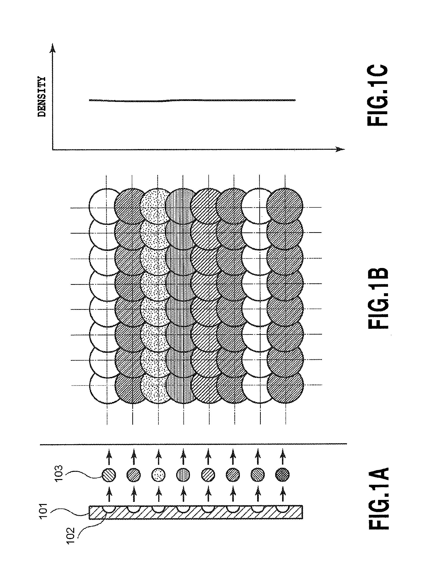
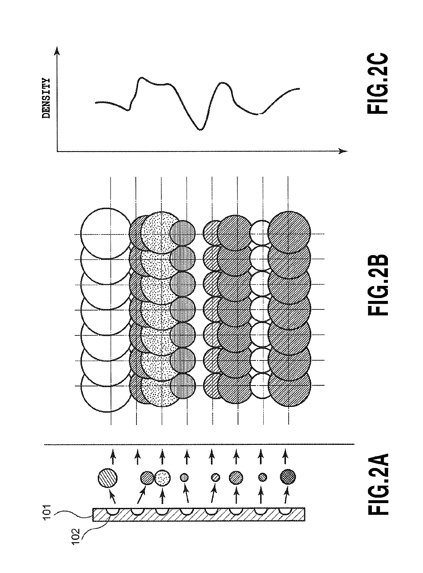
FIG. 19 is a diagram showing a density variation along the scan direction in a unit area of a printing result by the multi-scan printing method with control of printing time interval difference shown in FIG. 12.

In FIG. 19, an abscissa denotes the position in the scan direction and an ordinate denotes the density. Here, the density is an optical reflection density of an image printed on a printing medium and is a result of measuring the density o...


PUM


Abstract

After a first scan in a forward direction, conveying corresponding to one nozzle block is performed, and then in a second scan in a backward direction, printing of a “printing area 1,” which is a unit area, is completed. Then after completion of printing of the unit area, conveying corresponding to 14 nozzle blocks is performed. Then by reciprocal third and fourth scans, printing of a “printing area 2” is completed in a likewise manner. Subsequently, two scans in a reciprocal manner are performed in a likewise manner to perform printing of each unit area. In any unit area, printing time intervals between scans are such that, at a same position in a scan direction, the time interval is the same. Consequently, differences in density between unit areas that are adjacent in a conveying direction of a printing medium, that is, between-band unevenness becomes more difficult to recognize.

Description

BACKGROUND OF THE INVENTION1. Field of the InventionThe present invention relates to an inkjet printing apparatus and an inkjet printing method, and specifically relates to a configuration for reducing density unevenness that occurs when printing is performed by reciprocal, bidirectional scanning.2. Description of the Related ArtPersonal computers, word processors, and other office automation devices have come to be used widely in recent years, and various printing apparatuses are provided for printing out information processed by such devices. As a trend of such printing apparatuses, high image quality and high speed are being demanded, and various techniques for these purposes are provided.High Quality Image Printing TechnologiesAs an example of a high image quality technology, a so-called multi-scan method is known. With this method, scanning of a print head is performed a plurality of times on a same region and in the plurality of scans, different ink ejection ports are set to b...

Claims


Application Information

Patent Timeline
Patent Type & Authority Patents(United States)
IPC IPC(8): B41J29/38
CPCB41J19/145
Inventor TAKAHASHI, KIICHIROTESHIGAWARA, MINORUEDAMURA, TETSUYAMARU, AKIKOMURAYAMA, YOSHIAKINAKANO, TAKATOSHITAIRA, HIROSHI
Owner CANON KK
Why Eureka
Try Eureka