Optical scanning apparatus and image fomring apparatus equipped with the same

Inactive Publication Date: 2005-12-08
CANON KK
View PDF2 Cites 2 Cited by
  • Summary
  • Abstract
  • Description
  • Claims
  • Application Information

AI Technical Summary

Benefits of technology

[0033] According to the present invention, in an optical scanning apparatus using a short-wavelength light source, it is possible to reduce streaks in an image or unevenness in density of an image caused by influences of dusts, scratches and toner etc. on the surface of reflecting members by appropriately arranging the number and positions of the reflecting members such as turn bac

Problems solved by technology

The image forming apparatus shown in FIG. 11 is disadvantageous in terms of size reduction and cost saving, since there are many useless spaces (the hatched portions) in the apparatus and many scanning lenses are required to shorten the optical path length.
Therefore, employment of the blue-violet laser directly leads to the problem of unevenness in density of an image caused by small particles such a

Method used


Image

  • Optical scanning apparatus and image fomring apparatus equipped with the same
  • Optical scanning apparatus and image fomring apparatus equipped with the same
  • Optical scanning apparatus and image fomring apparatus equipped with the same

Examples


first embodiment

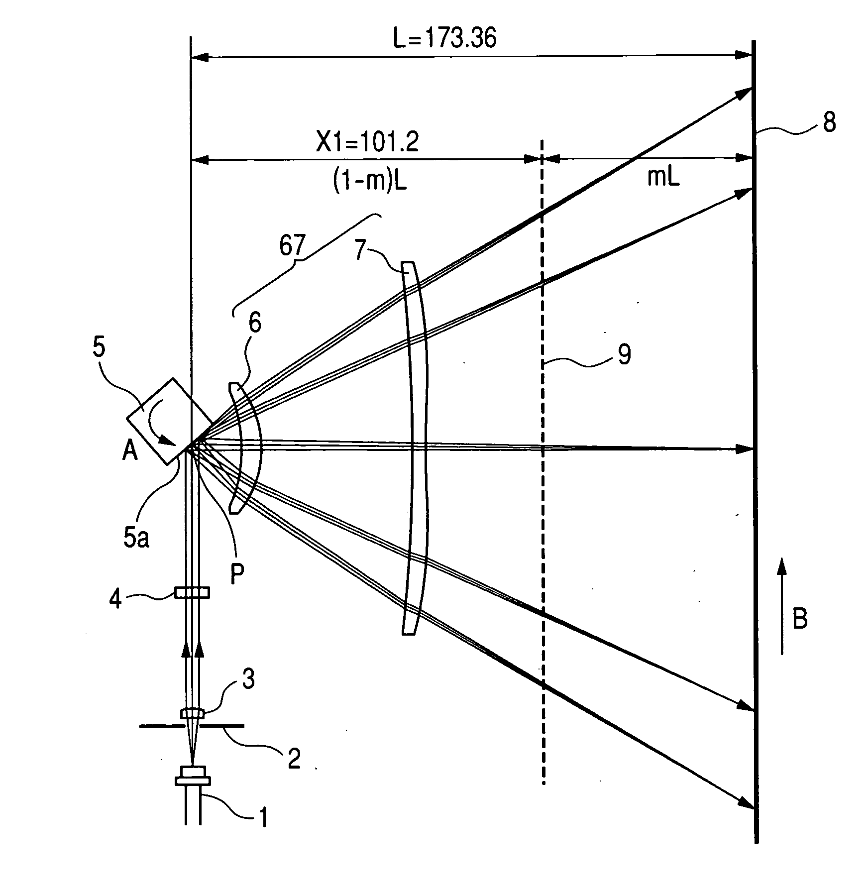
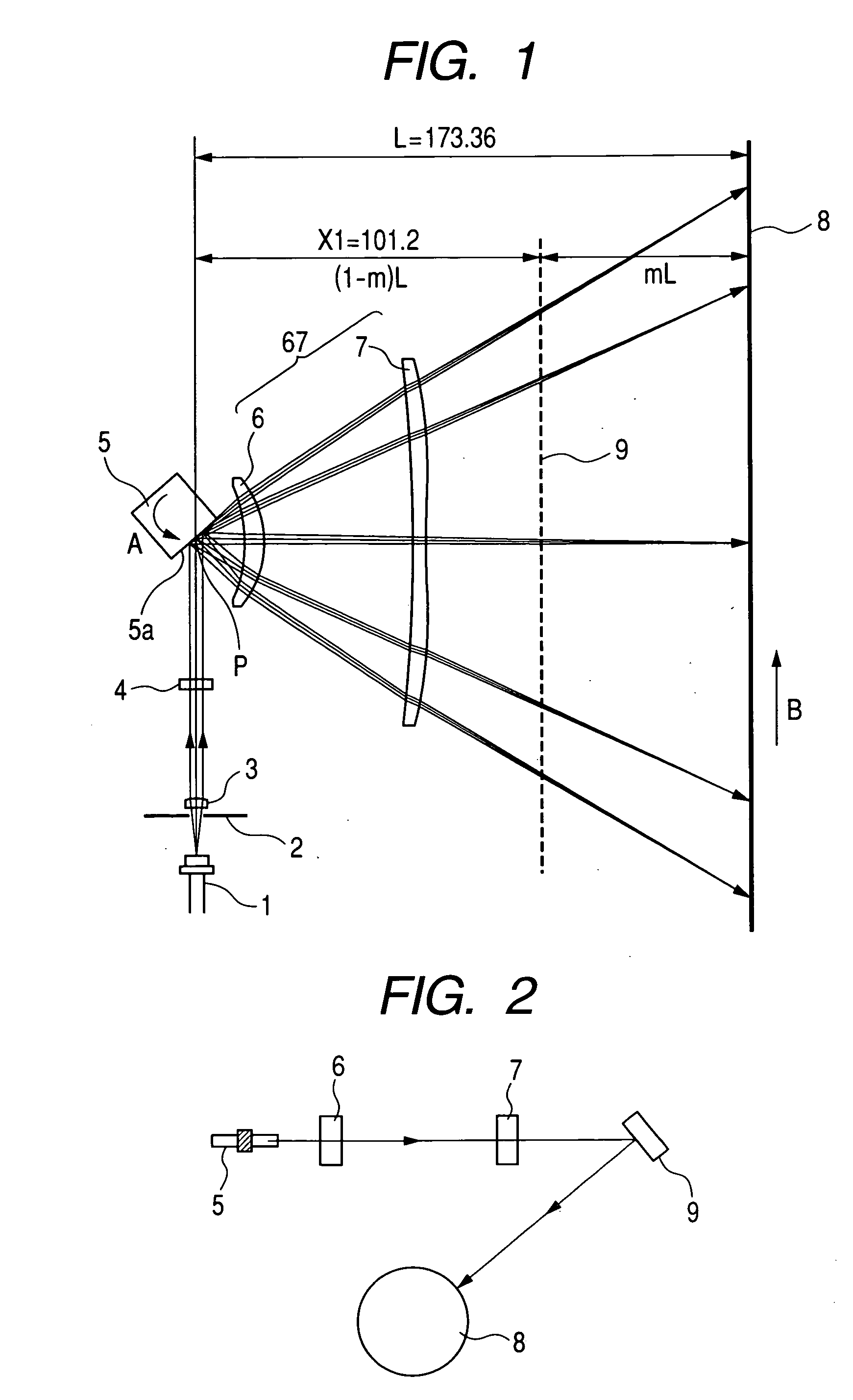
[0057]FIG. 1 is a cross sectional view taken on a main scanning cross section (in the main scanning direction) (or a main scanning cross sectional view) showing the principal portion of an optical scanning apparatus according to the first embodiment of the present invention. FIG. 2 is a cross sectional view taken on a sub-scanning cross section (in the sub-scanning direction) (or a sub-scanning cross sectional view) showing the principal portion of the optical scanning apparatus according to the first embodiment of the present invention.

[0058] Here, the main scanning direction refers to the direction orthogonal to the rotation axis of deflecting means and to the optical axis of a scanning optical element (that is, the direction in which the light beam is reflected and deflected (or deflected and scanned)), and the sub-scanning direction refers to the direction parallel to the rotation axis of the deflecting means. The main scanning cross section refers to the plane that is parallel...

second embodiment

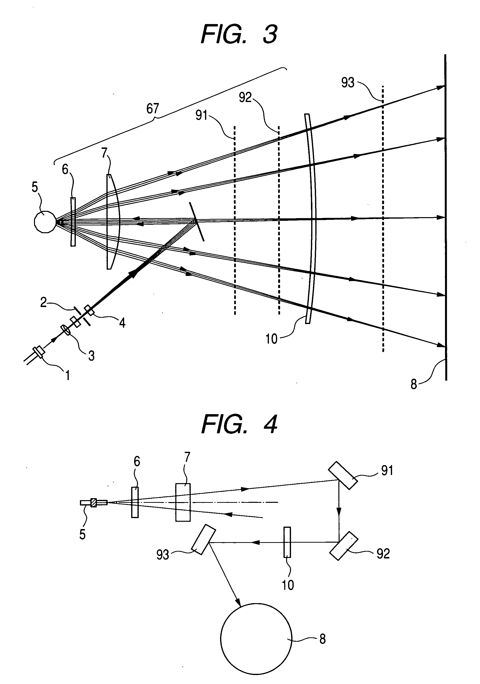
[0089]FIG. 3 is a cross sectional view in the main scanning direction (or a main scanning cross section) showing the principal portion of the second embodiment of the present invention. FIG. 4 is a cross sectional view in the sub-scanning direction (or a sub-scanning cross section) showing the principal portion of the second embodiment of the present invention. In FIGS. 3 and 4, elements the same as those shown in FIGS. 1 and 2 are designated by the same reference numerals.

[0090] What is different in this embodiment from the above-described first embodiment is that the incidence optical system is composed of an overfilled scanning optical system (OFS) and that the reflection means is composed of three turn back mirrors 91, 92 and 93. The other structures and optical functions are substantially the same as those in the first embodiment, and the same advantageous effects are achieved by them.

[0091] Specifically, in this embodiment, a light beam emitted from the light source means 1 ...

third embodiment

[0106]FIG. 6 is a cross sectional view in the main scanning direction (or a main scanning cross sectional view) showing the principal portion of the third embodiment of the present invention. FIG. 7 is a cross sectional view in the sub-scanning direction (or a sub-scanning cross sectional view) showing the principal portion of the third embodiment of the present invention. In FIGS. 6 and 7, elements the same as those shown in FIGS. 1 and 2 are designated by the same reference numerals.

[0107] What is different in this embodiment from the first embodiment described before is that the diameter of an aperture stop 82 is configured so that set the spot size in the main scanning cross section is set to 30 μm and the spot size in the sub-scanning cross section is set to 35 μm and that the reflecting means is composed of two turn back mirrors 91 and 92. The other structures and optical functions are substantially the same as those in the first embodiment, and the same advantageous effects ...


PUM


Abstract

An optical scanning apparatus in which streaks in an image or unevenness in density of an image caused by influences of dusts, scratches and toner etc on the surface of a reflecting member are unlikely to occur and excellent images can be always obtained and an image forming apparatus equipped with such an optical scanning apparatus are to be achieved. The apparatus comprises a first optical system for guiding a light beam emitted from light source unit to deflecting unit, the deflecting unit for reflecting and deflecting the light beam from the first optical system, a second optical system for guiding the light beam reflected and deflected by the deflecting unit onto a surface to be scanned through reflecting unit including n (n is an integer equal to or larger than 1) reflecting members. The apparatus satisfies the following conditions for the F-number Fnomain (mm) with respect to a main scanning cross section of an exit side of the second optical system and the smallest beam area Smin (mm2) among beam areas on reflecting surfaces of the n reflecting members on which a light beam is reflected during traveling on the optical axis of the second optical system: 70<Fnomain, and (0.004/Smin)×n<0.03.

Description

BACKGROUND OF THE INVENTION [0001] 1. Field of the Invention [0002] The present invention relates to an optical scanning apparatus and an image forming apparatus equipped with the same. More particularly, the present invention is suitably applied to an image forming apparatus, such as a laser beam printer or a digital copying machine using an electrophotography process and a multifunction printer, in which image information is recorded by optically scanning a surface to be scanned by means of a scanning optical system having fθ characteristics with a light beam emitted from a light source and deflected by a polygon mirror serving as a light deflector. [0003] 2. Related Background Art [0004] In scanning optical apparatuses such as laser beam printers, a light beam is modulated in accordance with an image signal and emitted from a light source, then is periodically deflected by a light deflector composed of, for example, a rotary polygon mirror (or a polygon mirror), and is converged ...

Claims


Application Information

Patent Timeline
IPC IPC(8): B41J2/47B41J2/44G02B13/00G02B26/10G02B26/12G03G15/04H01J5/16H04N1/036H04N1/113
CPCG02B26/125B41J2/471
Inventor SHIMOMURA, HIDEKAZU
Owner CANON KK
Why Eureka
Try Eureka