Recording method and recording apparatus capable of reducing streaks and unevenness in image density

a recording method and image density technology, applied in the field of recording methods and equipment, can solve problems such as prone to problems, uneven density of recorded images, and inability to uniformly follow the main scanning direction, and achieve the effect of removing image defects

Inactive Publication Date: 2007-01-18
CANON KK
View PDF11 Cites 1 Cited by
  • Summary
  • Abstract
  • Description
  • Claims
  • Application Information

AI Technical Summary

Benefits of technology

[0023] In view of the problems set forth above, it is an object of the present invention to provide an ink jet recording method and apparatus realizing a process that is able to eliminate image defects, including density unevenness described above, in a subsequent scan for recording.
[0024] The present invention is featured in that, by reading a density of an image, not yet completed, in a preceding scan of recording and reflecting the result of the reading on a subsequent scan of recording, streaks and density unevenness occurred in the preceding scan of recording are reduced in the subsequent scan of recording. More specifically, based on the result of the reading, recording data for use in the subsequent scan of recording is corrected so as to reduce streaks and density unevenness.

Problems solved by technology

In ink jet recording techniques, one problem to be overcome for achieving higher image quality is a variation in ink droplets discharged from an ink jet recording head.
It is also known that the variation in ink discharge causes the following problems.
(2) If there is a variation in the amount of discharged ink for each of the discharge ports, the sizes and densities of dots formed on recording paper are varied and hence density unevenness appears in a recorded image.
(3) If there are variations in the direction and the amount of ink discharged through one discharge port, the positions, sizes and densities of dots formed in the main scanning direction on recording paper are varied, thus resulting in that a line in the main scanning direction may be not uniform, or a recorded image may provide a rough feel when looked at.
This problem is apt to occur with a bubble jet method in which ink is discharged by utilizing thermal energy, particularly, among various discharge methods used in ink jet recording techniques.
However, such a method gives rise to problems that the production cost is increased and the production yield is reduced.
However, the disclosed method has a problem as follows.
Accordingly, a plurality of processing steps must be carried out whenever the correction process is executed, and maintainability of the device deteriorates.
Furthermore, when a user has recorded an image without noticing a reduction in image quality caused by deterioration with time, the ink, the recording paper, and the time required for the recording are wasted.
In addition, the disclosed method is not effective when the direction and the amount of ink discharged through one discharge port vary for each of the discharge ports.
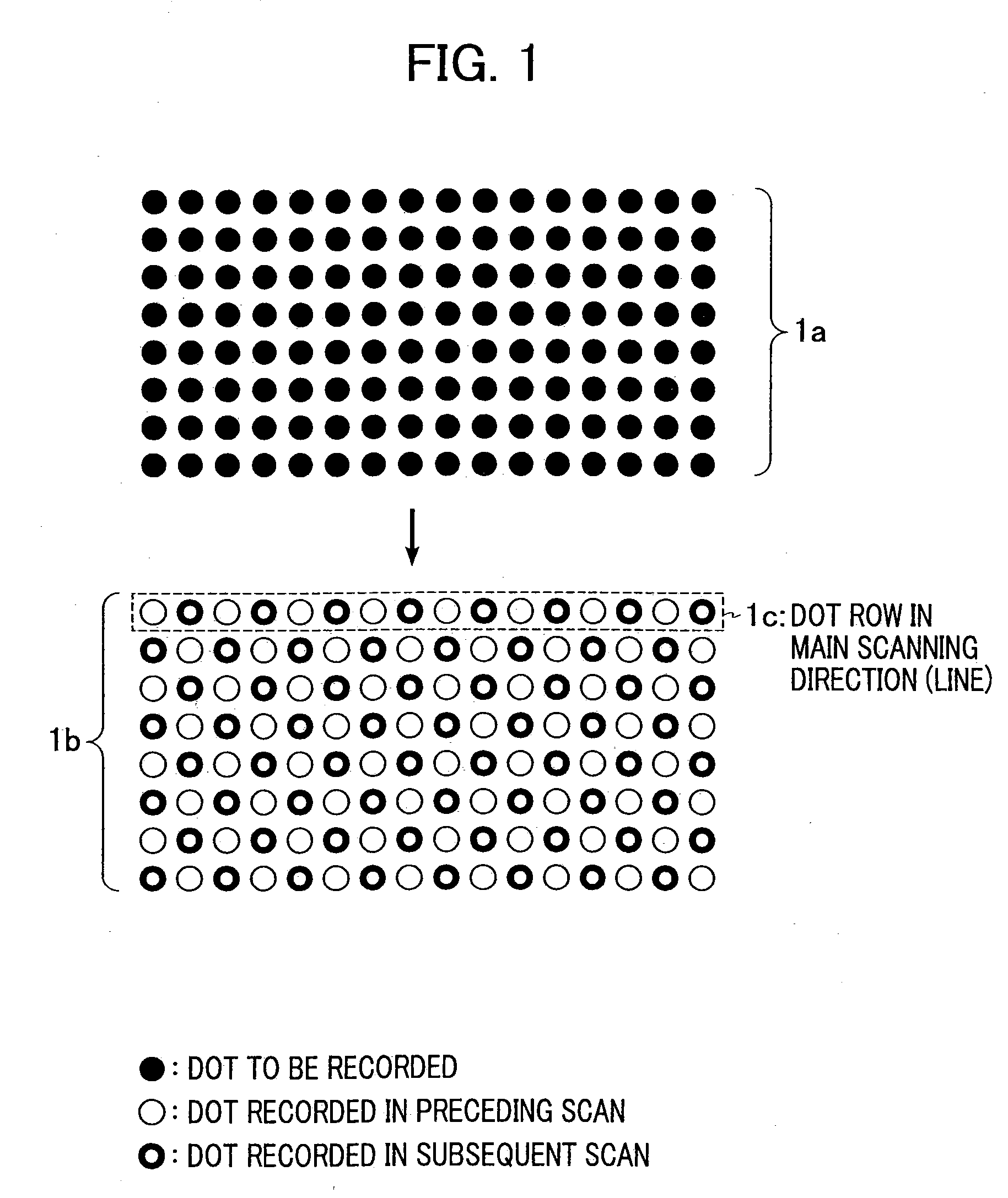
However, the method shown in FIG. 1 has a problem as follows.
Therefore, the effect of reducing streaks and density unevenness is not obtained in such a case.
Further, since the method shown in FIG. 1 is intended to reduce streaks and density unevenness based on statistics and probability approaches by employing ink droplets from plural sets of discharge ports to average the directions and the amounts of discharged ink, it is not ensured that streaks and density unevenness are always reduced.
For example, if the discharge directions of ink droplets from two discharge ports forming the same line are both curved in the same direction, or if the amounts of ink discharged through the two discharge ports are both reduced, the effect of reducing streaks and density unevenness cannot be obtained.
In addition, the method shown in FIG. 1 is not sufficiently effective when the direction and the amount of ink discharged through one discharge port vary for each of the discharge ports.
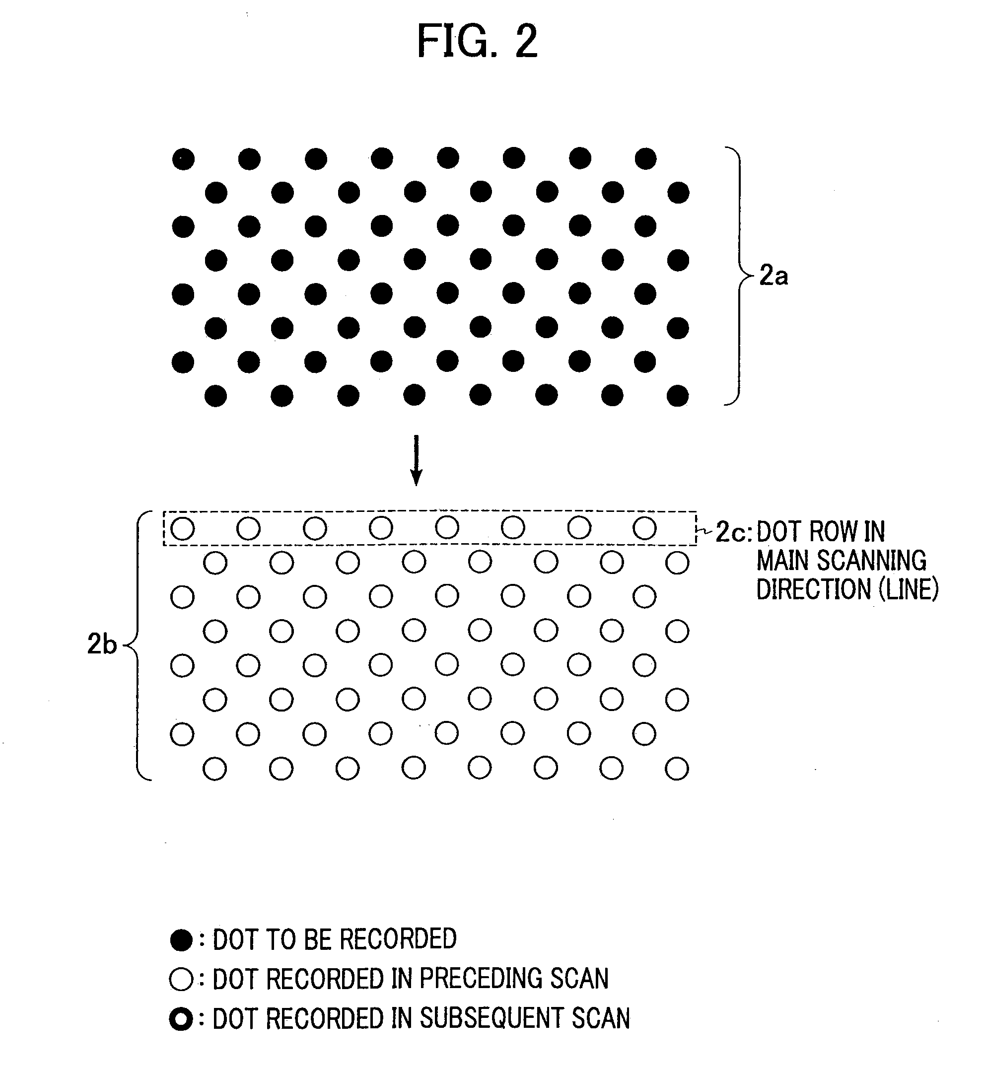
Even with the method disclosed in the above-cited U.S. Pat. No. 5,430,479, however, since streaks and density unevenness are reduced based on statistics and probability approaches by employing ink droplets from a plurality of discharge ports to average the directions and the amounts of discharged ink, it is also not ensured that streaks and density unevenness are always reduced.
In addition, the method disclosed in the above-cited U.S. Pat. No. 5,430,479 is also not sufficiently effective when the direction and the amount of ink discharged through one discharge port vary for each of the discharge ports.
Regarding U.S. Pat. No. 6,547,361, it is to be noted that this patent discloses the method for locating the positions of recording failures and performing correction recording in a subsequent scan, but this patent does not sufficiently disclose the process for creating correction data which is effective to satisfactorily reduce streaks and density unevenness in addition to correction of the recording failures.

Method used


Image

  • Recording method and recording apparatus capable of reducing streaks and unevenness in image density
  • Recording method and recording apparatus capable of reducing streaks and unevenness in image density
  • Recording method and recording apparatus capable of reducing streaks and unevenness in image density

Examples


first embodiment

[0050]FIG. 6 is a representation for explaining a combination of a feed amount of recording paper and a discharge port used in each scan. In FIG. 6, reference numeral 1 illustrates the recording head. In this example, a total of 16 discharge ports N1 to N16 are divided into four groups, and recording is made by allocating dots to be recorded to four scans.

(First to Third Scans)

[0051] First, in a first scan, only the discharge ports N13 to N16 are employed and ink droplets are discharged through those discharge ports which are allocated in accordance with the input image data. The term “image data” means information representing in which positions on recording paper dots are to be recorded at what a level of density. A manner of determining from the image data whether the ink droplets are to be discharged in the current scan, i.e., a binary coding process, can be implemented by any suitable one of known methods, such as simple binary coding, dithering, a method using a mask, and a...

second embodiment

[0060] In this second embodiment, an image is formed by four scans as in the first embodiment described above, but deep ink droplets are used in the recording made by the first and second scans, light ink droplets are used in the recording made by the third and fourth scans. Further, in this second embodiment, ink droplets are discharged for one pixel in six patterns, i.e., “no ink droplets”, “only one light ink droplet”, “two light ink droplets”, “only one deep ink droplet”, “one deep ink droplet and one light ink droplet”, and “two deep ink droplets”. These six patterns enable the recording to be made at 6 levels of gradation per pixel. FIG. 8 is an illustration for explaining the above six patterns. More specifically, FIG. 8 shows the six patterns at levels of 0 to 5, which are formed by applying a light ink dot 8a and a deep ink dot 8b to the area of one pixel. Note that positions where the dots are applied in one pixel are not limited to those shown in FIG. 8. For example, the ...

third embodiment

[0065] A third embodiments will be described below in connection with an example in which ink droplets are discharged in plural sizes different from each other and an image is formed by three scans. In the recording operation carried out by the printer according to this third embodiment, an image is formed in the first and second scans by discharging ink droplets each having a large discharge volume, while an image is formed in the third scan by discharging an ink droplet having a small discharge volume.

[0066] Further, in this third embodiment, ink droplets are discharged for one pixel in five patterns (at 5 levels of gradation), i.e., “no ink droplets”, “one ink droplet having a small discharge volume”, “one ink droplet having a large discharge volume”, “two ink droplets each having a large discharge volume”, and “two ink droplets each having a large discharge volume and one ink droplet having a small discharge volume”. Usually, however, the first four patterns (i.e., 4 levels of ...


PUM


Abstract

A recording method for use in a recording system for completing an image by multiple scans of a recording head includes the steps of reading an image recorded by a predetermined number of scans among the multiple scans of the recording head except at least the last scan, and correcting, based on a result of reading the image in the reading step, data for an image to be recorded by one or more scans subsequent to the predetermined number of scans. An image is correctively recorded by performing one or more scans subsequent to the predetermined number of scans in accordance with the corrected data.

Description

BACKGROUND OF THE INVENTION [0001] 1. Field of the Invention [0002] The present invention relates to an ink jet recording method and apparatus. More particularly, the present invention relates to an ink jet recording method and apparatus capable of reducing streaks and unevenness in recording density and forming an image with good quality. [0003] 2. Description of the Related Art [0004] An ink jet (IJ) recording method is widely used because of advantageous features, i.e., a high speed, high image quality, and a low running cost. Recently, with development of information infrastructures such as computer hardware / software and networks, a higher speed and higher image quality have been demanded. [0005] In ink jet recording techniques, one problem to be overcome for achieving higher image quality is a variation in ink droplets discharged from an ink jet recording head. Such a variation occurs, for example, in the amount of ink discharged and the discharge direction of ink droplets. It ...

Claims


Application Information

Patent Timeline
Patent Type & Authority Applications(United States)
IPC IPC(8): B41J29/38B41J2/01B41J2/21B41J29/393
CPCB41J29/393B41J2/2132
Inventor SHIOYA, MAKOTO
Owner CANON KK
Why Eureka
Try Eureka