Image processing apparatus, control method of image processing apparatus, image forming apparatus, and storage medium

a control method and image processing technology, applied in the field of image processing apparatus, can solve the problems of color misregistration, image forming apparatus often suffers a tilt and curvature of scanning lines, color misregistration, etc., and achieve the effect of removing density unevenness

Inactive Publication Date: 2014-07-22
CANON KK
View PDF22 Cites 1 Cited by
  • Summary
  • Abstract
  • Description
  • Claims
  • Application Information

AI Technical Summary

Benefits of technology

[0019]The present invention has been made in consideration of the aforementioned problems, and provides a technique for eliminating density unevenness generated in an image to be formed based on image data by modifying correction values corresponding to pixels including a specific pattern of those to be applied to the image data so as to correct misregistration of a scanning line.
[0023]According to the present invention, the technique for eliminating density unevenness generated in an image to be formed based on image data by modifying correction values corresponding to pixels including a specific pattern of those to be applied to the image data so as to correct misregistration of a scanning line can be provided.

Problems solved by technology

However, an image forming apparatus often suffers a tilt and curvature of a scanning line due to various causes generated by a printing mechanism.
More specifically, a position of an actual scanning line by the deflection scanning unit displaces from its ideal position, that is, misregistration occurs.
As a result, when toner images are transferred onto a transfer member or printing material to be superposed on each other, relative positions of these images are displaced, thus causing color misregistration, that is, image quality deterioration.
However, since such mechanical adjustment requires a high-precision adjustment device and movable members, cost may increase, and it is difficult to apply this technique to an inexpensive personal image forming apparatus.
In this case, it is difficult for the technique described in Japanese Patent Laid-Open No. 2003-241131 to adjust a scanning line for respective colors.
However, when the correction based on the method of Japanese Patent Laid-Open No. 2004-170755 is applied to image data of a fine line image including fine lines, a line width of the fine line image to be formed may suffer unevenness.
Also, when this correction is applied to image data of a fine image including regular patterns with a high spatial frequency, the fine image to be formed may suffer density unevenness.
Furthermore, upon forming a dot having a size not more than one dot, such unevenness is caused by the influence of nonlinear factors during processes of exposure-development-transfer-fixing.
When this density change is periodically generated in an image, stripe-like density unevenness becomes conspicuous, resulting in image quality deterioration.
Furthermore, in the electrophotography image forming apparatus, it is difficult to stably form dots especially in an area formed by only dots with a small size like scanning positions p3 to p7 in FIG. 22C.
This is because dot sizes formed based on the corrected image data become uneven according to the scanning positions.
As in the case of the fine line image, since such density change periodically occurs in the image, stripe-like density unevenness becomes conspicuous, resulting in image quality deterioration.
In general, the characteristics of the electrophotography system as a cause of density unevenness change depending on conditions such as a temperature, humidity, degree of degradation of an image forming device, and the like.
For this reason, measurements using a sensor have to be made for different conditions, thus increasing a down time.
Also, density unevenness which may occur in an image to be formed may change depending on a pattern of the image.
For this reason, various pattern images have to be formed, and measurements have to be done for the respective formed pattern images, thus increasing a consumption amount of toner used to form the pattern images in addition to an increase in down time.
Furthermore, density unevenness which may occur in an image to be formed appears as very small density changes.
In order to measure such very small density changes, a high-precision sensor is required, resulting in an increase in cost.

Method used


Image

  • Image processing apparatus, control method of image processing apparatus, image forming apparatus, and storage medium
  • Image processing apparatus, control method of image processing apparatus, image forming apparatus, and storage medium
  • Image processing apparatus, control method of image processing apparatus, image forming apparatus, and storage medium

Examples


first embodiment

[0049]The first embodiment will explain a tandem type 4-drum, multi-color image forming apparatus which adopts an intermediate transfer belt based on an electrophotography system as an application example of the present invention.

[0050]

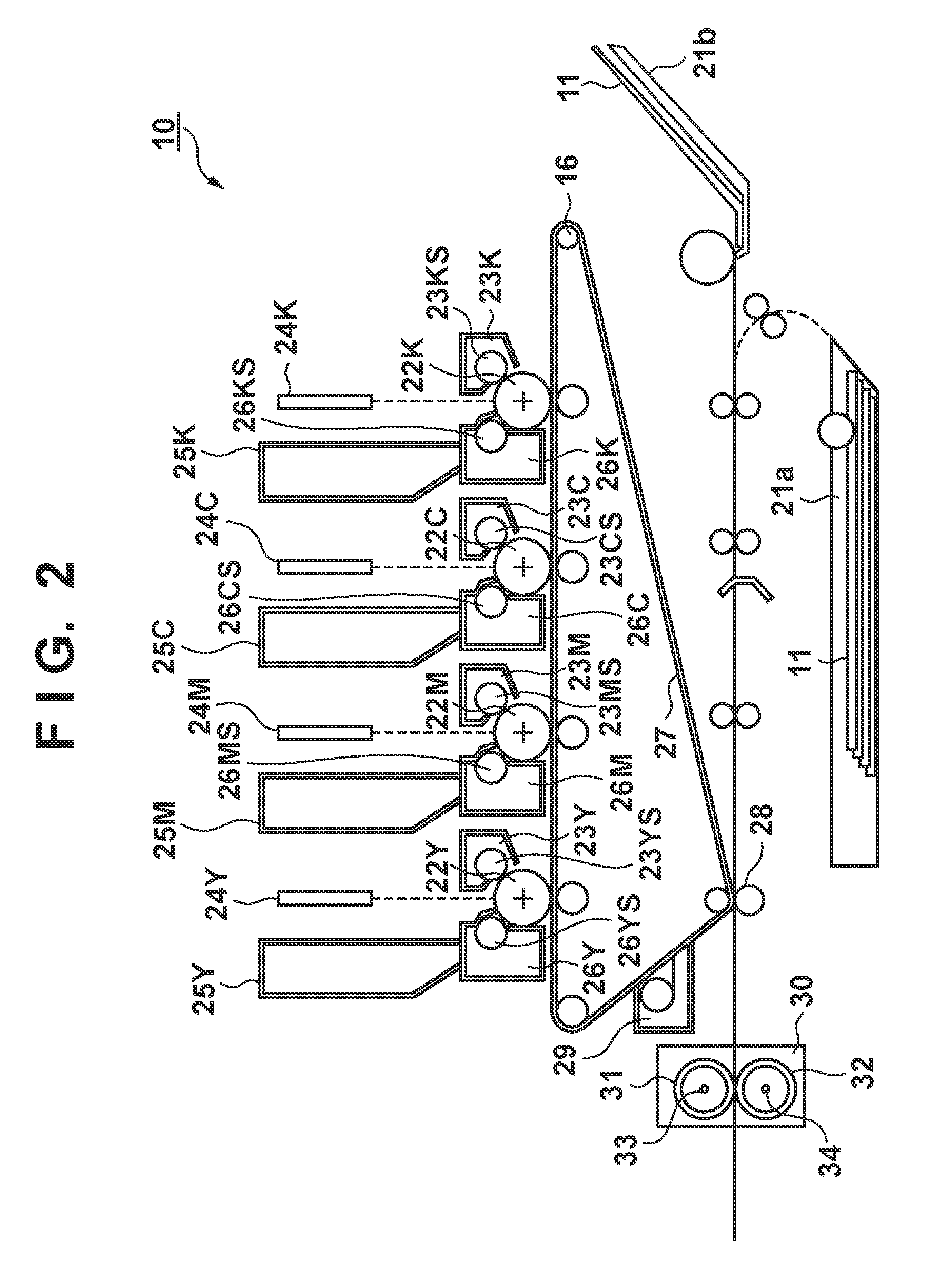
[0051]The arrangement of an image forming apparatus 10 will be described first with reference to FIG. 2. In this embodiment, the image forming apparatus 10 is a color image forming apparatus which forms an image at a resolution of 600 dpi. The image forming apparatus 10 forms electrostatic latent images respectively on surfaces of photosensitive drums (photosensitive members) 22Y, 22M, 22C, and 22K (to be described as “22Y, 22M, 22C, and 22K” hereinafter for the sake of simplicity; the same applies to other members) in accordance with an exposure control signal generated using pulse width modulation (PWM) by an image processing unit (an image processing unit 400 shown in FIG. 4). Since these electrostatic latent images are developed using toners of re...

first example

[0140]A case will be described first wherein misregistration correction is applied to image data of an input image including a thin line having a 2-dot width along the main scanning direction, as shown in FIG. 15A. In FIGS. 15A to 15E, respective pixel values (tone values) of the image data are expressed by numerical values ranging from 0 to 100(%). FIGS. 15B and 15C show results of the misregistration correction processing for partial regions of the image data shown in FIG. 15A. More specifically, FIGS. 15B and 15C respectively show the results of the misregistration correction processing without adding modulation amounts according to this embodiment to Δy for a region in which misregistration correction amounts Δy are near 0 (dot) and for that in which misregistration correction amounts Δy are near 0.5 (dots). Note that the misregistration correction processing includes the aforementioned coordinate conversion processing and tone conversion processing.

[0141]In the image data shown...

second example

[0144]Next, a case will be described below wherein the misregistration correction is applied to image data of a fine image in which dots are arranged checkerwise, as shown in FIG. 16A. FIGS. 16B and 16C show results of the misregistration correction processing for partial regions of the image data shown in FIG. 16A as in FIGS. 15A to 15E. More specifically, FIGS. 16B and 16C respectively show the results of the misregistration correction processing without adding modulation amounts according to this embodiment to Δy for a region in which misregistration correction amounts Δy are near 0 (dot) and for that in which misregistration correction amounts Δy are near 0.5 (dots). Note that the misregistration correction processing includes the aforementioned coordinate conversion processing and tone conversion processing.

[0145]In the image data shown in FIGS. 16B and 16C, although dot sizes on the image data appear to be equal to each other, dot sizes when they are visualized on printing mat...


PUM


Abstract

When an image processing apparatus of one aspect of this invention corrects input image data using correction values (misregistration correction amounts Δy), it determines whether or not image data to be corrected using amounts Δy includes a specific pattern which may cause density unevenness in an image to be formed. When the image processing apparatus determines that the image data includes the specific pattern, it modifies amounts Δy corresponding to pixels including the specific pattern of the amounts Δy using any of a plurality of different predetermined modulation amounts (modification values). Furthermore, the image processing apparatus corrects the image data for respective pixels using either the amounts Δy before modification, or the modified amounts Δy when the modification is done.

Description

BACKGROUND OF THE INVENTION[0001]1. Field of the Invention[0002]The present invention relates to an image processing apparatus, a control method of an image processing apparatus, an image forming apparatus, and a storage medium.[0003]2. Description of the Related Art[0004]In recent years, image quality enhancement of an output image and speeding-up of image formation are required more than ever for image forming apparatuses such as printers and copying machines which adopt an electrophotography system, inkjet system, and the like. Especially, in case of a multi-color image forming apparatus of the electrophotography system, a technique using a plurality of photosensitive members corresponding to different colors so as to attain speeding-up is known. Such image forming apparatus corresponds to a tandem type which attains multi-color printing by forming toner images of respective colors on respective photosensitive members, and transferring these toner images in turn from the photosen...

Claims


Application Information

Patent Timeline
Patent Type & Authority Patents(United States)
IPC IPC(8): G06K15/00H04N1/40
CPCG03G15/01G03G15/0189G03G15/5025G03G2215/0158
Inventor YAMAZAKI, HIROYUKI
Owner CANON KK
Why Eureka
Try Eureka