Recessed electrical device housing assembly and clip

a technology of electrical devices and housings, applied in the direction of substation/switching arrangement details, coupling device connections, basic electric elements, etc., can solve the problems of preventing the insertion of outlet boxes, wiring devices cannot be installed at low voltage device locations, and complex and expensive mold slides, etc., to facilitate the snap-fit of clips

Inactive Publication Date: 2011-12-06
PASS SEYMOUR
View PDF24 Cites 12 Cited by
  • Summary
  • Abstract
  • Description
  • Claims
  • Application Information

AI Technical Summary

Benefits of technology

[0015]According to the embodied invention, the clip includes a longitudinal body portion having opposite ends defining an N-gang length there between. The clip has a finger structure that is configured to engage a front and a rear surface of an edge of the sized opening. It further has N device mounting bores disposed between the opposite ends, each of which is aligned with a longitudinal centerline of each one of the N-gang-sized openings. According to a non-limiting aspect, the finger structure is located at each opposite end and provides a sliding engagement of the clip with opposing edges of the sized-opening. In an alternative, non-limiting aspect, the finger structure may be located along an edge of the clip body allowing the clip to engage an upper or lower edge of the sized-opening. According to non-limiting aspects, the clip body may be rigid or, alternatively, have a compressible section that facilitates a snap-fit of the clip in the sized-opening.

Problems solved by technology

The bosses intrude into the rectangular opening and although they accommodate the attachment of the low voltage device, this intrusion prevents the insertion of an outlet box.
As a result, a wiring device cannot be installed at the “low voltage device locations” even if the low voltage device opening size would accommodate a wiring device.
If the holes were not substantially parallel to the draw, very complex and expensive slides in the mold would be required.
This restriction on hole orientation thus limits the quantity and the orientation of low voltage openings.
These known boxes have to have at least one opening that is substantially parallel to the mounting flange of the TV wall box, otherwise low voltage device mounting holes cannot be molded into the box.
Conversely, low voltage openings cannot be angled with respect to the mounting flange since mounting holes cannot be provided at such locations.
The options currently available to the installer, however, are limited because of the dedicated nature of the openings as discussed above.
Whereas the family of boxes may address all foreseeable combinations, it is done so at considerable expense.
Another solution has been to provide an over-sized TV wall box having more openings, but this adds difficulty to the installation.
This solution is neither time- nor cost-efficient.
Unfortunately these marks are not always readily visible.
A smaller wall box would cause a screwdriver to misalign with respect to the mounting screw heads.
Other known TV wall boxes have a shallow-recessed, low voltage device opening, making these boxes unduly wide.
Unfortunately the wires may be routed between the two housings and become damaged as a result.
Another disadvantage is that a tool is required for fastening the adapter to the TV wall box, making the installation process more time-consuming.

Method used


Image

  • Recessed electrical device housing assembly and clip
  • Recessed electrical device housing assembly and clip
  • Recessed electrical device housing assembly and clip

Examples


Embodiment Construction

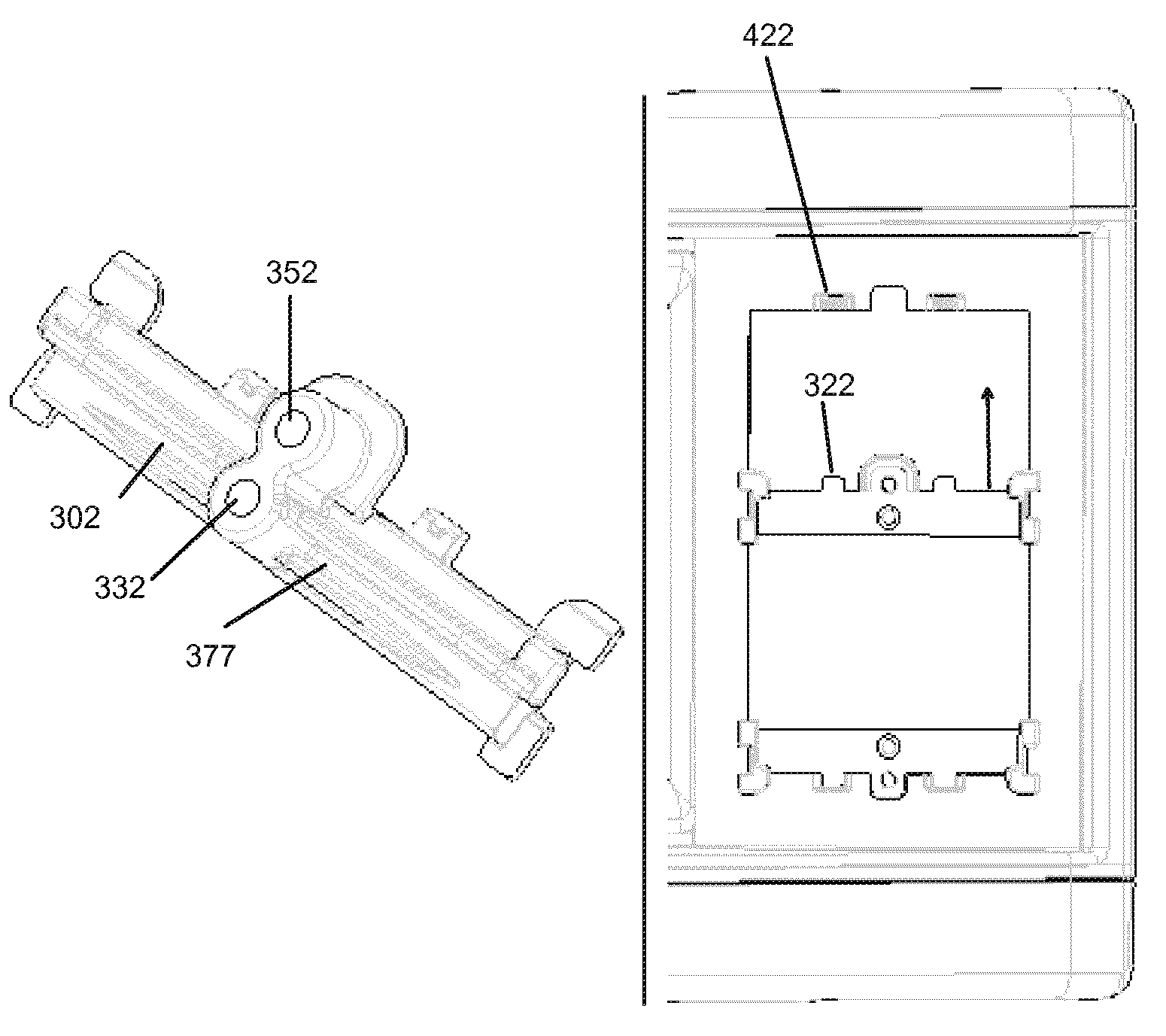
[0031]FIGS. 3(A-D) show, respectively, an upward-facing, front side elevational view, a top plan view, a downward-facing, rear-side elevational view, and a perspective view of a removable, uni-body, low voltage device adapter clip 300-1 (hereinafter ‘clip’) according to an embodiment of the invention. The clip is intended to be used in an electrical device housing having an opening (hereinafter ‘sized-opening’) that is sized to accommodate a standard N-gang outlet box. As shown in the figures, the clip 300-1 has a longitudinal body portion 302 having opposite ends 304 that define a standard N-gang length there between. As shown in FIG. 3, N=1 such that the clip is adapted to occupy a standard single-gang-sized opening. According to a non-limiting aspect of the embodiment, the clip 300-1 has a finger structure 306 integrally disposed at each of the opposite ends 304. The finger structure as illustrated in FIG. 3 is configured to slidingly engage a front and a rear surface (403, 404) ...


PUM


Abstract

A removable, uni-body, low voltage device adapter clip for an electrical device housing having an opening that is sized to accommodate a standard N-gang outlet box, makes it possible to mount a low voltage device in the sized-opening. The clip includes a longitudinal body portion having opposite ends defining an N-gang length there between. The clip has a finger structure that is configured to engage a front and a rear surface of an edge of the sized opening. It further has N device mounting bores disposed between the opposite ends, each of which is aligned with a longitudinal centerline of each one of the N-gang-sized openings. An electrical device housing assembly includes an electrical device housing having a plurality of recessed walls, wherein at least one of the walls has an opening that is sized to accommodate a standard N-gang outlet box, and a pair of removable, uni-body, low voltage device adapter clips. The assembly may include a low voltage device. The assembly may further include integrated mounting flanges and flange covers.

Description

RELATED APPLICATION DATA[0001]N / A.FIELD OF THE INVENTION[0002]Embodiments of the invention generally relate to electrical device assemblies and components. More particularly, an embodiment of the invention is directed to a removable adapter clip for mounting a low voltage device in an electrical device housing assembly designed to accommodate a wiring device. Another embodiment is directed to a housing assembly for electrical wiring devices that interchangeably accommodates both low voltage devices and electrical wiring devices.BACKGROUND OF THE INVENTION[0003]As used herein, the term “low voltage device” is meant to include, but is not limited to, coaxial sockets, telephone sockets, data sockets, RCA ports, HDMI ports, S-Video ports, low voltage ports, DC voltage ports, etc., as a person skilled in the art would understand to be low voltage devices.[0004]As used herein, the term “wiring device” is meant to include, typically single-gang, 120 V or 240 V receptacles, fixture ON / OFF s...

Claims


Application Information

Patent Timeline
Patent Type & Authority Patents(United States)
IPC IPC(8): H02B1/01
CPCH02G3/123
Inventor HABEREK, ANDREW M.
Owner PASS SEYMOUR
Why Eureka
Try Eureka