Cannula system and method of use

a technology of cannula and endoscope, which is applied in the field of system and method of endoscope navigation, can solve the problems of insufficient stent placement, insufficient stent placement, and insufficient stent placement,

Active Publication Date: 2011-12-13
INTUITIVE SURGICAL OPERATIONS INC
View PDF39 Cites 907 Cited by
  • Summary
  • Abstract
  • Description
  • Claims
  • Application Information

AI Technical Summary

Problems solved by technology

Unfortunately, even a reduced contact force has the potential for patient discomfort and tissue trauma.
An example of a potential operator error associated with an incremental advance system is that involving excessive advancement of an endoscope with a steerable tip within a rigidizable overtube.
Excessive advancement of the endoscope exposes a section of the endoscope that is not steerable and thus the tip may be inadvertently directed at a large contact angle against the wall of the body being explored.
Although the prior art teaches various methods for reducing contact discomfort, a large contact angle resulting from a poorly directed tip may be difficult to overcome.
The prior art frequently relies upon excessive advancement in combination with reaction forces from tissue walls to advance an instrument.

Method used


Image

  • Cannula system and method of use
  • Cannula system and method of use
  • Cannula system and method of use

Examples


Embodiment Construction

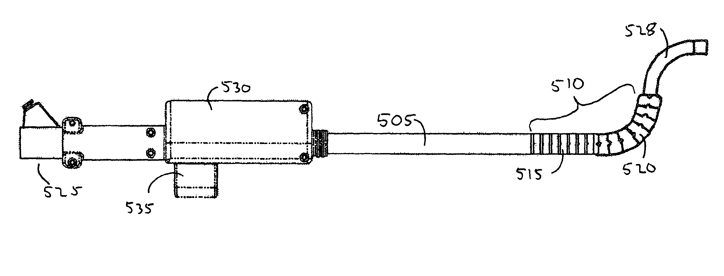
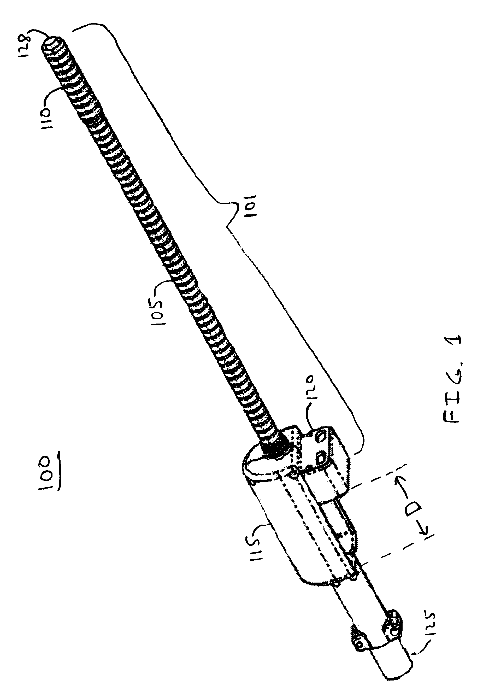
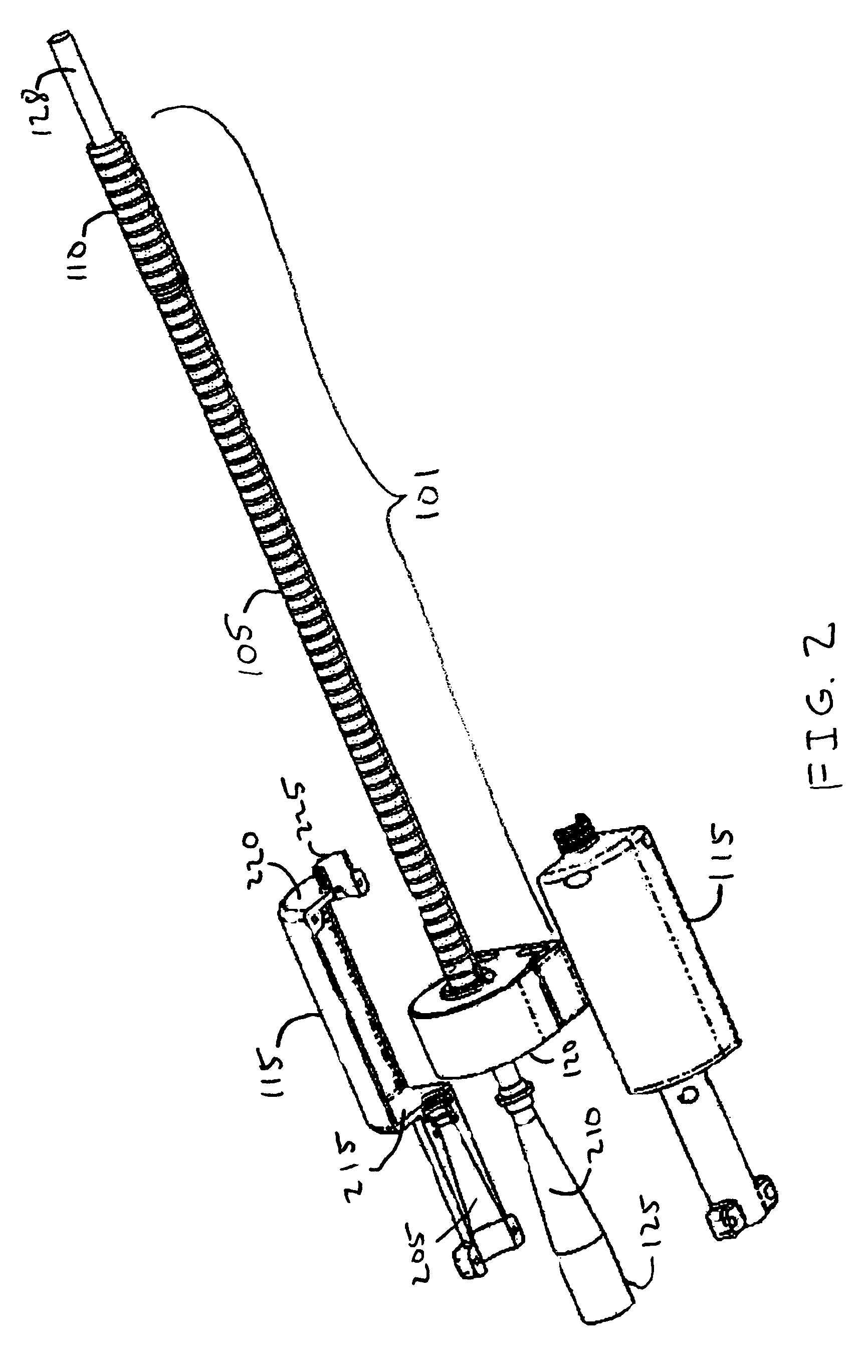
[0033]FIG. 1 shows an embodiment of a cannula system 100. A cannula 101 includes a rigidizing actuator 120. The actuator 120 is used to control the rigidity of the cannula 101. A displacement limiting coupling 115 couples the cannula 101 to an insertable device (e.g., an endoscope) 125. The displacement limiting coupling 115 aligns the axes of the endoscope 125 and the cannula 101, and allows a limited relative axial displacement “D” between the endoscope 125 and the cannula 101. The displacement limiting coupling slidably couples the cannula 101 to the insertable device 125. The insertable device may include a steerable tip 128.

[0034]A discussion of rigidizable structures for use in a cannula system may be found in the copending U.S. patent application Ser. No. 10 / 661,159, “Shape Transferring Cannula System and Method of Use”, by the inventor of the present invention, filed Sep. 12, 2003, and is incorporated herein by reference. The cannula 101 may include segments with independent...


PUM


Abstract

A cannula coupled to a displacement limiting coupling. The cannula includes at least one rigidizable segment and means for rigidizing the rigidizable segment. The displacement limiting coupling couples to an insertable device and aligns the axes of the insertable device and the cannula and establishes limits on the relative axial displacement between the cannula and the insertable device. The insertable device may have a steerable tip that maintains an overlap with the rigidizable segment due to the axial displacement limits.

Description

CROSS-REFERENCE TO RELATED APPLICATIONS[0001]This application is related to U.S. patent application Ser. No. 10 / 661,159, “Shape Transferring Cannula System and Method of Use”, by the inventor of the present invention, filed Sep. 12, 2003, and is incorporated herein by reference.BACKGROUND OF THE INVENTION[0002]1. Field of the Invention[0003]The present invention relates to devices, systems, and processes useful for exploration of hollow body structures, particularly those areas accessed through a tortuous, unsupported path. More particularly, the present invention relates to a system and method for navigation of an endoscope having a steerable tip.[0004]2. Description of Related Art[0005]Endoscopes are frequently used for medical exploratory procedures, either alone or in combination with an overtube for aiding the insertion of the endoscope. When an overtube is used it may be fully inserted in a single step prior to the insertion of the endoscope. The overtube and endoscope may als...

Claims


Application Information

Patent Timeline
Patent Type & Authority Patents(United States)
IPC IPC(8): A61B1/00
CPCA61B1/00154A61B1/0055A61B2019/2238A61B2034/306
Inventor VARGAS, JAIME S.
Owner INTUITIVE SURGICAL OPERATIONS INC
Why Eureka
Try Eureka