Connection system comprising an external cable guide on wiper motor housings

a technology of wiper motor and connection system, which is applied in the direction of vehicle maintenance, vehicle cleaning, transportation and packaging, etc., can solve the problems of cable pulling off, complicated gear mechanism cover production, and cable pulling off, so as to improve functional reliability and easy to adapt

Inactive Publication Date: 2011-12-13
ROBERT BOSCH GMBH
View PDF12 Cites 39 Cited by
  • Summary
  • Abstract
  • Description
  • Claims
  • Application Information

AI Technical Summary

Benefits of technology

[0008]The object of the invention is to specify a connection system for electrically connecting two components which are arranged at a distance from one another on a motor assembly, in particular for connecting control contacts to wiper motors, which connection system is distinguished by a low level of outlay on installation and improved functional reliability as compared to the prior art and can be easily adapted to changing connection requirements.
[0009]The invention concerns a connection system comprising an external cable guide for electrically connecting at least two components which are arranged at a distance from one another on a motor assembly and whose positions in relation to the housing parts of the motor assembly are fixed. The connection system according to the invention comprises at least one electrical line, which connects the components which are arranged on the motor assembly, and a supporting element on the outside of the housing of the motor assembly, which supporting element determines the geometric profile of the electrical line. Since the geometric profile of the electrical line is determined, the disadvantages of cables which run freely across the outside of the motor assembly can be avoided by defining a suitable profile for the cables. In this case, the profile of the electrical line is selected such that the risk of damage during the fitting and servicing processes which are to be expected is avoided. In addition, the supporting element itself at least partially protects the electrical line from shock and external effects.
[0011]It is advantageous when the supporting element is a plastic channel which is connected to at least one housing part of the motor assembly. The connection to the housing part ensures adequate fixing in position, the design of the supporting element as a channel permits encapsulated line guidance, this making the system particularly insensitive to damage to the electrical lines.
[0014]A similarly advantageous refinement of a connection according to the invention is provided when the supporting element is connected firmly to a plugging adapter which is arranged between a plug, by means of which connection is made with the motor assembly, and a plugging slot which is located on the motor housing. An adapter of this kind can be used to match the connection system to specific customer requests with a low level of outlay, without having to change the plugging slot on the motor assembly. If the supporting element and the associated electrical lines are connected to the adapter, this produces a component which has all the functions of the system according to the invention and can be quickly replaced or installed. Particularly in this case, it is advantageous when the supporting element is releasably connected to at least one housing part of the motor assembly by means of a plurality of connecting elements.
[0015]If it is not necessary to change over the connection system quickly, said supporting element may be adhesively bonded to at least one housing part of the motor assembly, this providing a particularly robust design which also virtually prevents the supporting element being accidently engaged in from behind and prevents the damage associated with this.

Problems solved by technology

The variant with metal strips running in the gear mechanism cover complicates production of the gear mechanism cover and, when changes are needed or there are defects in the contact-connection to the control contacts, always requires replacement of the entire gear mechanism cover.
The variant with cables which run freely across the outside of the motor assembly is associated, in particular, with the risk of damage to the cables due to operation-related shock effects or other external effects, this possibly leading to the cables being pulled off and functional faults resulting from this.

Method used


Image

  • Connection system comprising an external cable guide on wiper motor housings
  • Connection system comprising an external cable guide on wiper motor housings
  • Connection system comprising an external cable guide on wiper motor housings

Examples


Embodiment Construction

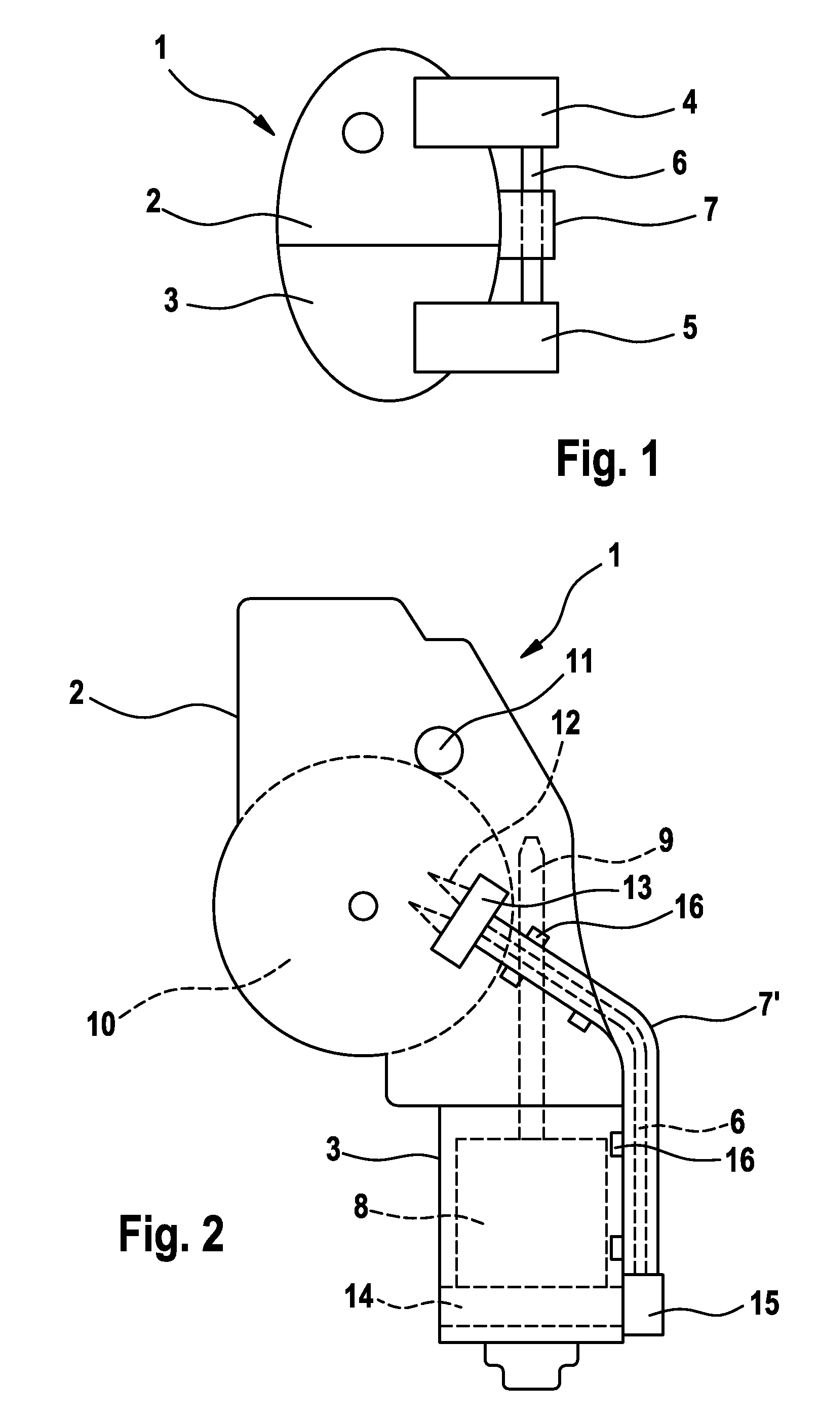
[0022]FIG. 1 shows the basic structure of a connection system according to the invention comprising an external cable guide. Said connection system is arranged on a motor assembly 1 with a plurality of housing parts 2, 3 and comprises two components 4 and 5 which are arranged at a distance from one another and whose positions in relation to the housing parts 2, 3 of the motor assembly 1 are fixed. The two components 4, 5 are connected by an electrical line 6, with a supporting element 7, which determines the geometric profile of the electrical line 6, being arranged on the outside of the housing 2, 3 of the motor assembly 1.

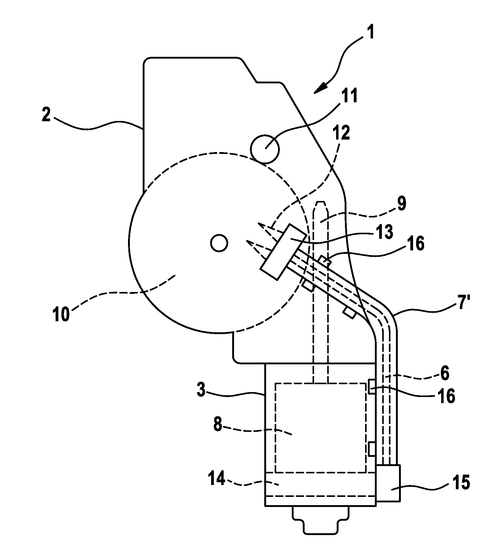
[0023]FIG. 2 shows a connection system according to the invention with a plastic channel 7′ as a supporting element. The motor assembly 1 has the typical shape of a wiper drive which is in the form of an individual drive and which has a wheel crank mechanism. However, use of the invention is in no way restricted to such wiper drives.

[0024]An electric motor 8 is l...


PUM


Abstract

The invention relates to a connection system comprising an external cable guide for electrically connecting at least two components (4, 5) that are arranged at a distance from each other on a motor subassembly (1), the positions of said components being fixed in relation to the housing parts (2, 3) of the motor subassembly (1). Said connection system also comprises at least one electric cable (6) connecting the components (4, 5) that are arranged on the motor subassembly (1) and a support element (7) on the outer side of the housing (2, 3) of the motor subassembly (1) that defines the geometric path of the electric cable (6).

Description

BACKGROUND OF THE INVENTION[0001]The invention relates to a connection system comprising an external cable guide on wiper motor housings, as can be used, in particular, for making contact between control contacts and wiper motors in vehicles.[0002]An established way of using electric motors as drives of wiper systems is embedding an electric motor in a complex assembly, called motor assembly in the text which follows, which, in addition to the actual motor, comprises gear mechanism components, housing parts, fixing means and electrical connection means. In this case, the electrical connection means are frequently arranged in the immediate vicinity of the motor parts with which contact is to be made, in order to be able to realize short conduction paths. An important constituent part of these electrical connection means, by means of which power is supplied to the electric motor during the operating phases, are so-called carbon brushes which are arranged in a brush holder. The brush h...

Claims


Application Information

Patent Timeline
Patent Type & Authority Patents(United States)
IPC IPC(8): H02K11/00
CPCB60S1/08B60S1/166H02K11/0068H02K11/0015H02K5/225H02K7/1166H02K11/21H02K11/30H02K5/22
Inventor BOHN, ROLANDHUESGES, MARIOLAUK, DETLEFSTERNS, ORLANDO
Owner ROBERT BOSCH GMBH
Why Eureka
Try Eureka