Object verification method for use in radar systems for motor vehicles

a technology for radar systems and objects, applied in the direction of reradiation, measurement devices, instruments, etc., can solve the problem of extremely rare cases, and achieve the effect of reliable elimination of ghost objects

Active Publication Date: 2011-12-13
ROBERT BOSCH GMBH
View PDF23 Cites 23 Cited by
  • Summary
  • Abstract
  • Description
  • Claims
  • Application Information

AI Technical Summary

Benefits of technology

[0010]The present invention provides for a more reliable elimination of ghost objects, in particular in the context of small object distances.
[0014]Although the probability of a ghost object being erroneously interpreted as a real object is relatively low when the conventional method is employed, statistically, the probability of a “shadow” also still existing for this ghost object is even many times lower. Thus, the reliability of the object verification is substantially enhanced in this manner.
[0018]When working with an angularly resolving radar system, the transverse offset of an object, i.e., the position of the object relative to one's own vehicle in the direction normal to the direction of travel, is calculated from the distance and the measured azimuth angle. Thus, the differential between the real object and its shadow also makes it possible to use the correct distance as a basis for calculating the transverse offset of the real object.

Problems solved by technology

However, such a “shadow” exists only for real objects and, typically, not for ghost objects.
In practice, however, such a case is extremely rare.

Method used


Image

  • Object verification method for use in radar systems for motor vehicles
  • Object verification method for use in radar systems for motor vehicles
  • Object verification method for use in radar systems for motor vehicles

Examples


Embodiment Construction

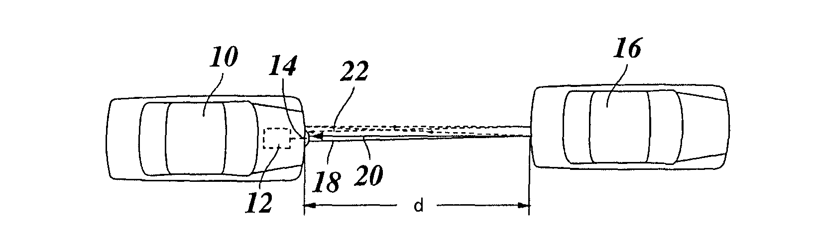
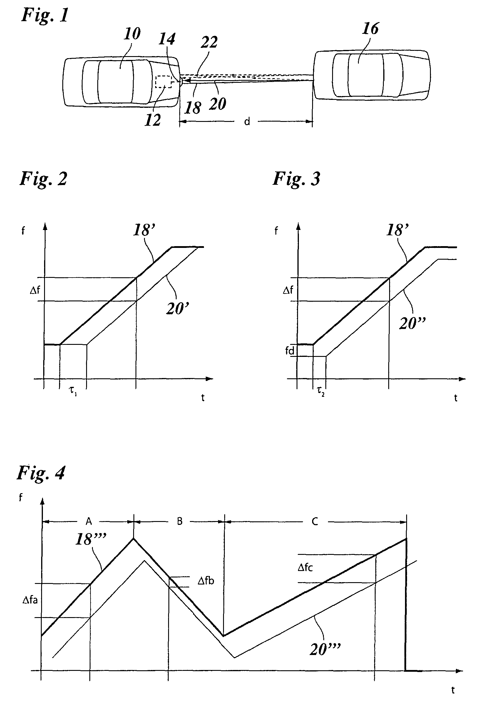
[0026]FIG. 1 schematically depicts a vehicle 10 which is equipped with a driver assistance system 12, e.g., a collision avoidance system, and an associated radar system. Of the radar system, merely a radar sensor 14 is shown, which is installed at the front of the vehicle in order to find the position of objects in the near field of vehicle 10. As an example of such an object, another vehicle 16 is shown.

[0027]Radar sensor 14 transmits a signal 18, which, for example, has a frequency on the order of 77 GHz, and which propagates in the forward direction in the form of a cone. Once it has covered a distance corresponding to distance d of the vehicles, signal 18 is reflected off of the back part of vehicle 16 and, in the process, undergoes a Doppler shift which is dependent on the relative velocity of the two vehicles. Reflected signal 20 propagates back towards radar sensor 14 where it is received. However, a portion of reflected signal 20 does not impinge again on radar sensor 14, bu...


PUM


Abstract

In an object verification method for use in radar systems for motor vehicles, the distances and relative velocities of located objects are determined on the basis of received radar echoes. The signature of multiple reflections is searched for in the received radar echoes to verify real objects.

Description

BACKGROUND OF THE INVENTION[0001]1. Field of the Invention[0002]The present invention relates to an object verification method for use in radar systems for motor vehicles, in which the distances and relative velocities of located objects are determined on the basis of received radar echoes.[0003]2. Description of Related Art[0004]In driver assistance systems for motor vehicles, radar systems are used for sensing the surrounding field of traffic, in particular for finding the position of vehicles traveling up ahead and potential obstacles in the near field of one's own vehicle. A typical application example is an ACC system (adaptive cruise control) for automatically controlling the distance to a vehicle in front of one's own vehicle. Moreover, driver assistance systems are being developed, whose primary purpose is to enhance traffic safety. These include automatic collision warning systems or collision avoidance systems, which automatically trigger an emergency braking in response t...

Claims


Application Information

Patent Timeline
Patent Type & Authority Patents(United States)
IPC IPC(8): G01S13/93G01S13/00G01S13/931
CPCG01S13/345G01S13/931G01S13/584G01S2013/9375G01S13/347G01S2013/93271
Inventor RANDLER, MARTINJORDAN, RUEDIGER
Owner ROBERT BOSCH GMBH
Why Eureka
Try Eureka