Object recognition apparatus and object recognition method using epipolar geometry

a technology of object recognition and epipolar geometry, applied in the field of object recognition technology, can solve the problems of inability to reconstruct the structure of the curved surface portions of objects, inability to accurately mount the camera, and inability to calculate the position coordinates

Active Publication Date: 2011-12-13
AISIN SEIKI KK
View PDF7 Cites 11 Cited by
  • Summary
  • Abstract
  • Description
  • Claims
  • Application Information

AI Technical Summary

Benefits of technology

[0014]Furthermore, an object recognition method processing images, as acquired by an imaging means mounted on a moving object, in a first image plane and a second image plane having different points of view, and recognizing an object in the vicinity of the moving object, also falls within the scope of the present invention; such an object recognition method comprises: a step of detecting feature points of a object image in the first image plane and the second image plane; a step of determining a fundamental matrix expressing a geometrically corresponding relationship, based on translational camera movement, between the first image plane and the second image plane, from not less than two pairs of feature points corresponding between the first image plane and the second image plane, on the basis of calculation of epipoles through auto-epipolar property; and a step of calculating a three-dimensional position of the object based on the coordinates of the object in the first image plane and the second image plane and the determined fundamental matrix. It goes without saying that such an object recognition method can achieve the same essential effects as the abovementioned object recognition apparatus of the present invention, and the same advantageous effects can be obtained therefrom.
[0015]In addition, a program that causes a computer to execute such an object recognition method, a medium on which such a program is recorded, and the like also fall within the scope of the present invention.
[0016]These and other features, advantages, and the like shall be made clear through the following descriptions and drawings referred to therein which illustrate an exemplary embodiment of the present invention.

Problems solved by technology

With this object recognition technology, it is necessary to arrange the left and right cameras in an accurate position so as to obtain a stereo image; deviation in the position of the left and right cameras leads to error in the calculation of position coordinates.
With this object recognition technology, image planes from before and after movement of a single camera are used, and thus accuracy in mounting the camera is not particularly demanded.
However, in order to find the position coordinates of the object, the position coordinates of the object are calculated based on the amount of displacement between corresponding parts of the object image in the first image plane and the second image plane, and the object is reconstructed; therefore, there is a problem in that the structure of the curved surface portions of the object cannot be reconstructed.
Note that this problem also arises in the technology disclosed in Patent Document 1.
With this method, not less than 8 pairs of corresponding points are necessary in order to find the F-matrix, and thus a problem arises, particularly when applying this method to an object recognition apparatus for a moving object such as an automobile, in that stable detection and tracking is difficult.

Method used


Image

  • Object recognition apparatus and object recognition method using epipolar geometry
  • Object recognition apparatus and object recognition method using epipolar geometry
  • Object recognition apparatus and object recognition method using epipolar geometry

Examples


Embodiment Construction

[0017]First, the theoretical background of the present invention shall be explained.

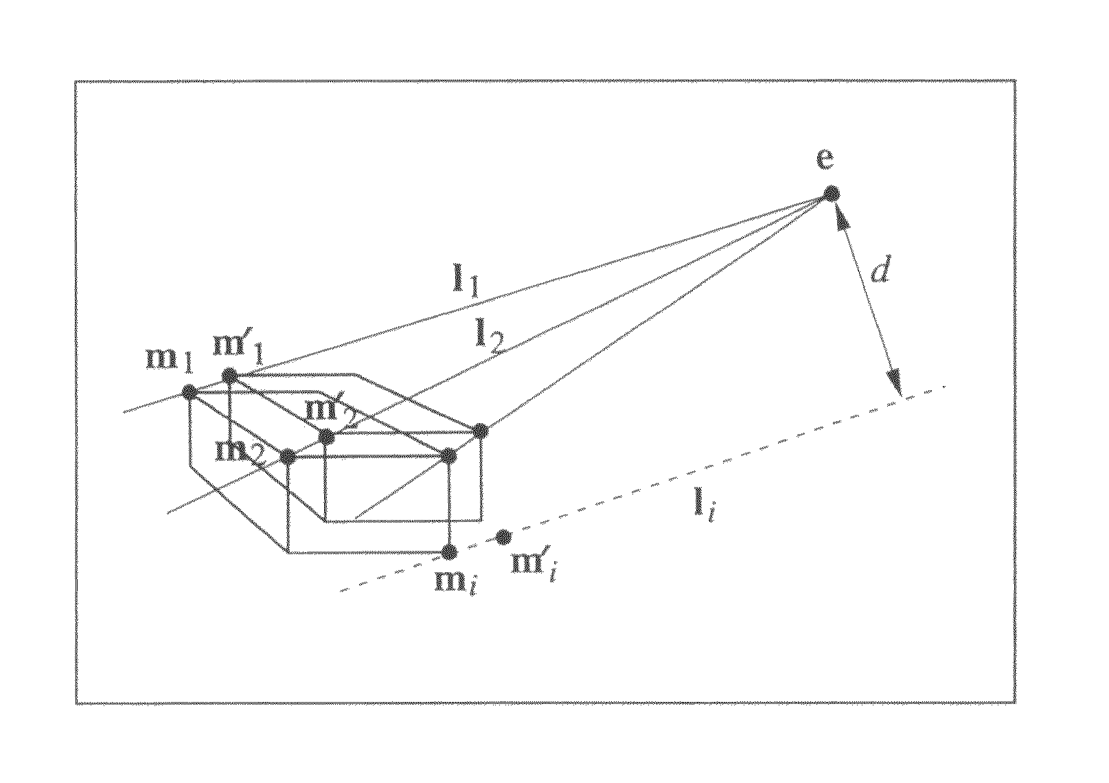
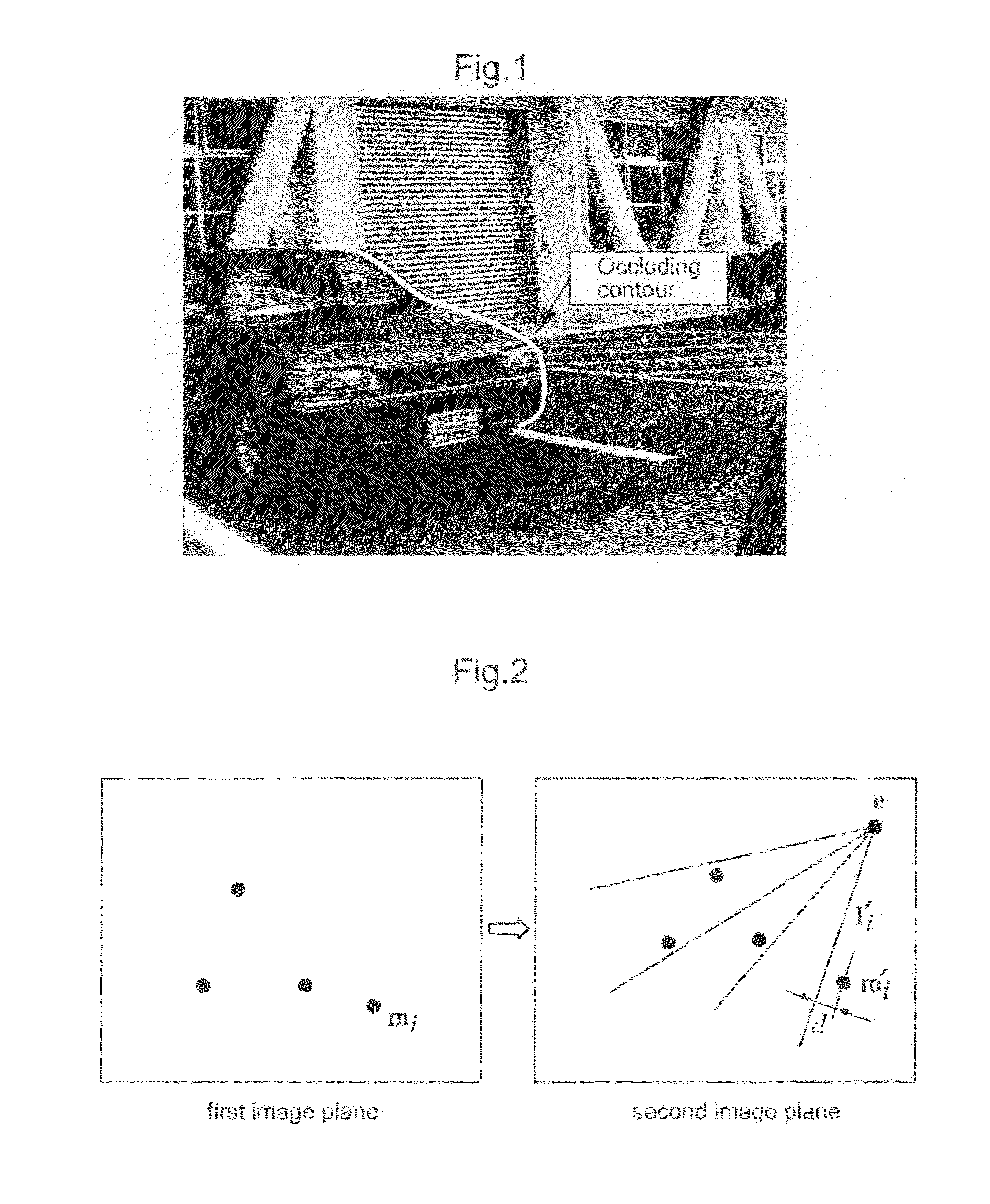
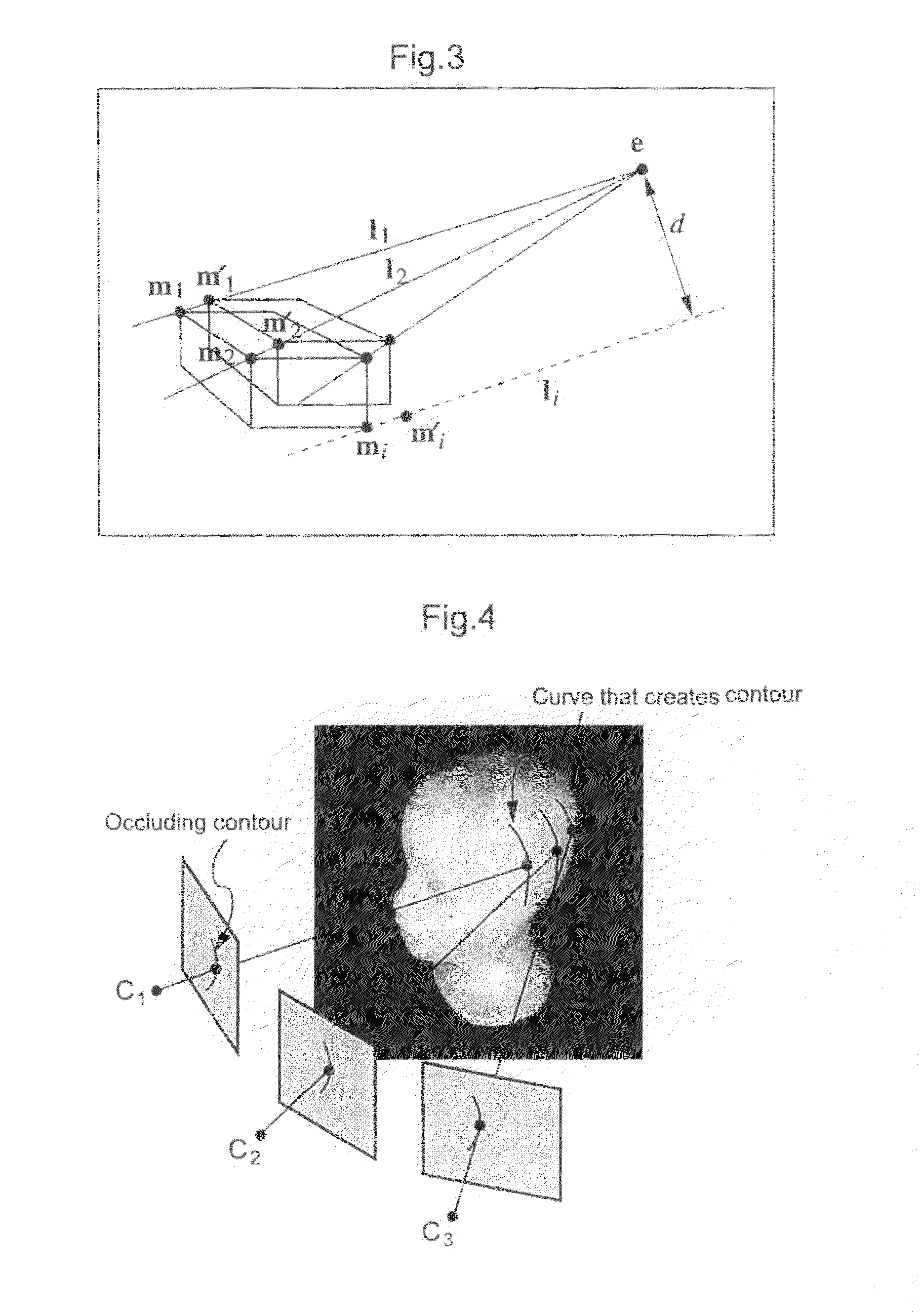
[0018]In the present invention, occluding contours are used as the main image feature of the object to be detected (hereafter, also referred to simply as “target object”) acquired by the imaging means. The “occluding contours” are, as shown in FIG. 1, contours arising in the image in which the target object occludes the background. Even when a target object has no surface texture, such occluding contours can be observed as long as a luminance difference between the target object and the background is present; therefore, the occluding contours can be used as an image feature for the target object regardless of the presence / absence of textures. However, many objects are made up of curved surfaces; therefore, occluding contours differ from feature points such as corners in that lines are curved, and thus it is difficult to find the correspondence between points on occluding contour curves obtained from ...


PUM


Abstract

An object recognition apparatus that processes images, as acquired by an imaging means (10) mounted on a moving object, in a first image plane and a second image plane of different points of view, and recognizes an object in the vicinity of the moving object. The object recognition apparatus comprises: a feature point detection means (42) that detects feature points in first and second image planes of an object image; a fundamental matrix determination means (43a) that determines, based on calculation of an epipole through the auto-epipolar property, a fundamental matrix that expresses a geometrically corresponding relationship based on translational camera movement, with not less than two pairs of feature points corresponding between the first and second image planes; and a three-dimensional position calculation means (43b) that calculates a three-dimensional position of an object based on the coordinates of the object in the first and second image planes and the determined fundamental matrix.

Description

TECHNICAL FIELD[0001]The present invention relates to object recognition technology that processes images, as acquired by an imaging means mounted on a moving object, in a first image plane and a second image plane of different points of view, and recognizes an object in the vicinity of the moving object.BACKGROUND ART[0002]A technology used in an object recognition apparatus is known, in which a first image plane and a second image plane of different points of view are created by two cameras arranged parallel to one another on the left and right with a predetermined space in between; the amount of displacement between corresponding parts of the object image in the respective image planes is calculated; and the perpendicular length from the object to a straight line that connects the left and right cameras is found based on the amount of displacement using the principle of triangulation (for example, refer to Patent Document 1). With this object recognition technology, it is necessa...

Claims


Application Information

Patent Timeline
Patent Type & Authority Patents(United States)
IPC IPC(8): G06K9/00G06K9/46G01C5/00G01C3/08G06K9/50B60Q1/00G01C3/00G06V10/147
CPCG01C11/00G06K9/00812G06K9/209G06T7/0075G06K9/00805G08G1/16G06T7/2033G06T2207/10016G06T2207/30264G08G1/165G08G1/168G06T7/593G06T7/246G06V20/586G06V20/58G06V10/147
Inventor KAKINAMI, TOSHIAKISATO, JUN
Owner AISIN SEIKI KK
Why Eureka
Try Eureka