
Chair type massager

a massager and chair technology, applied in the field of chair massagers, can solve the problems of taking a predetermined time to tilt the backrest part backward, affecting the massage effect, so as to prevent obstruction of the bloodstream and tiredness, prevent excessive pressure of the airbag, and maintain the effect of airbag pressure properly

Active Publication Date: 2011-12-27
MATSUSHITA ELECTRIC WORKS LTD
View PDF6 Cites 4 Cited by
  • Summary
  • Abstract
  • Description
  • Claims
  • Application Information

AI Technical Summary

Benefits of technology

[0006]The present invention provides a chair type massager which is capable of performing an arm stretch by holding and fixing the arms to be comfortable while realizing a space-saving and economical configuration, without deteriorating a massage feeling.
[0008]In accordance with the present invention, when the backrest part is tilted to execute the stretching, since the air supply into the air bags for holding arms is intermittently performed, the pressure of the air bags can be properly maintained without being excessively increased. Therefore, the defects such as the oppressive sensation on arms, the obstruction of the bloodstream and the tiredness are prevented, so that the arm stretch can be comfortably performed. Furthermore, since an expensive pressure retaining valve is not required, the massager is realized in a space-saving and inexpensive configuration.

Problems solved by technology

The massagers of the aforementioned JP-A-2005-013463 and JP-A-2005-152260, however, have following problems, when the arm stretch is performed.
However, it takes a predetermined time to tilt the backrest part backward until a user feels that the arms are stretched.
If the air is continuously supplied to the air bags to hold the arms while the predetermined time passes, the bloodstreams of the arms are obstructed so that the arms become tired and the massage feeling gets worse.
However, in such a case, a space is required for installing the pressure retaining valve.
Moreover, since the pressure retaining valve is expensive compared to the simple opening / closing valve, this causes an additional cost.

Method used


Image

  • Chair type massager
  • Chair type massager
  • Chair type massager

Examples


Embodiment Construction

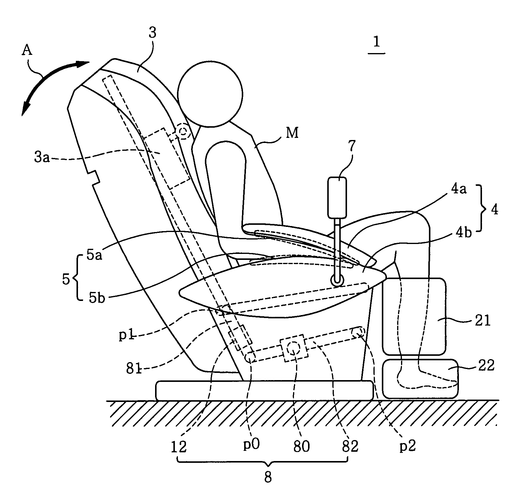
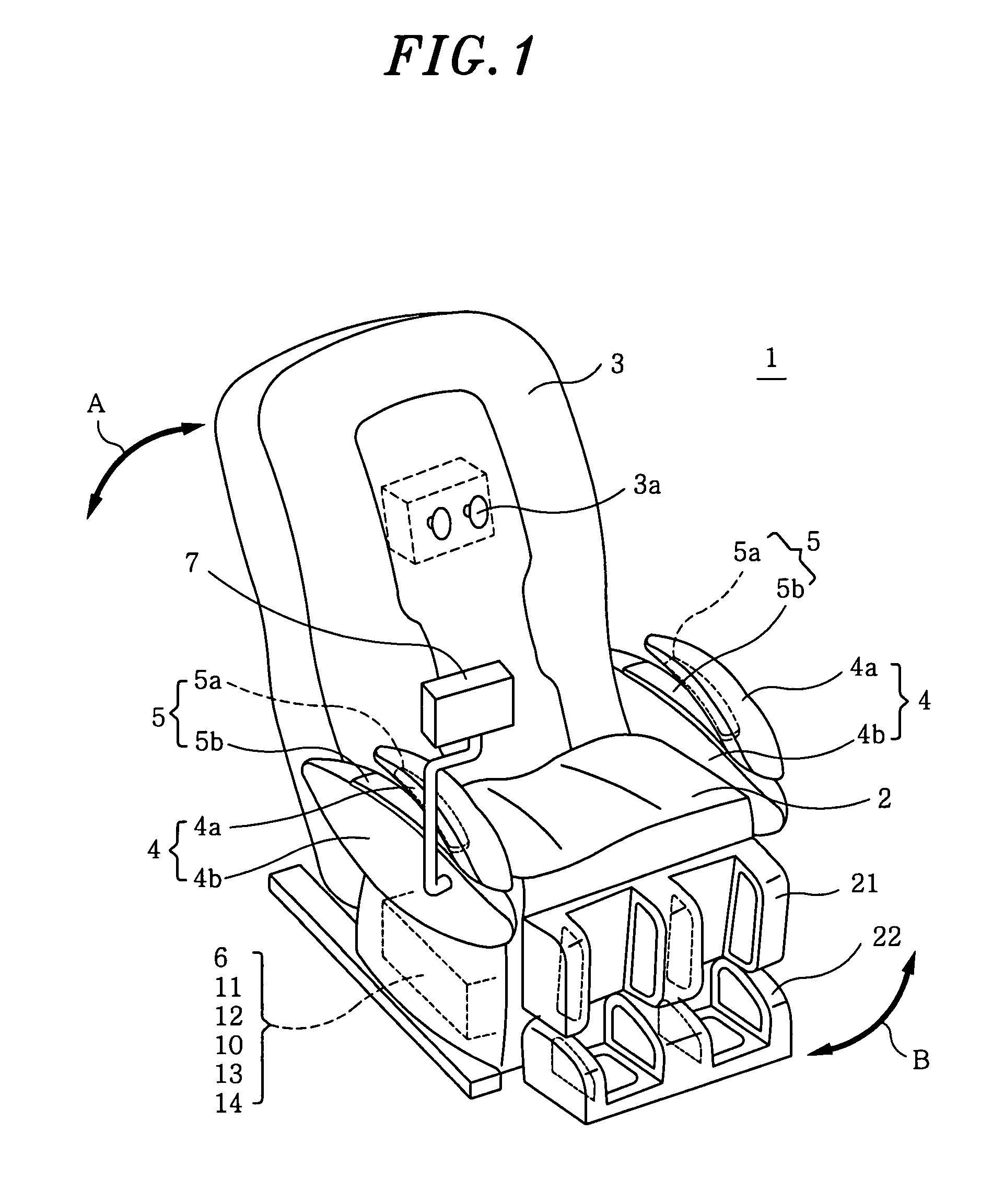
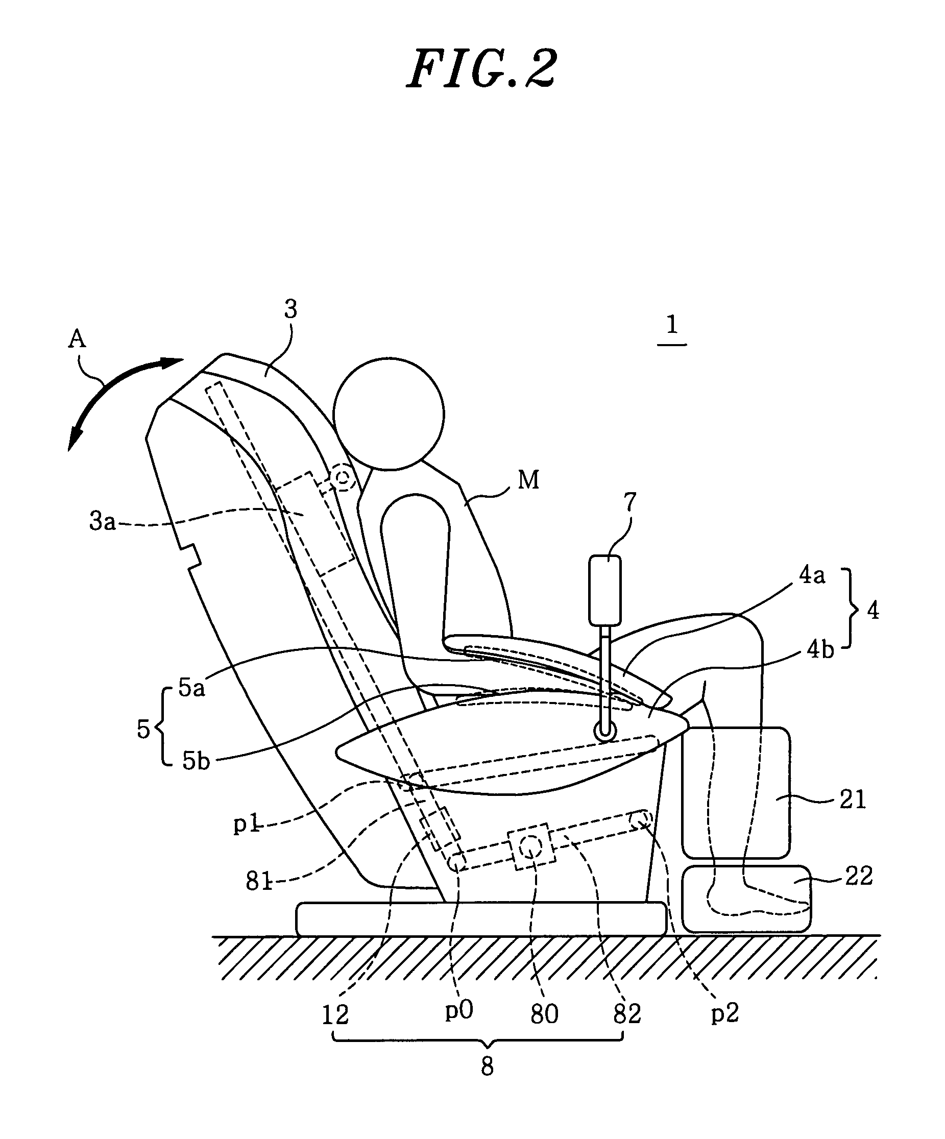
[0018]Hereinafter, exemplary embodiments of the present invention will be described in detail with reference to the accompanying drawings. FIG. 1 illustrates the appearance of a massager 1 in accordance with an embodiment of the present invention; FIG. 2 presents the massager on which a person M to be treated sits; FIG. 3 depicts a control block diagram of the massager 1; and FIG. 4 illustrates an air supply system for air bags of the massager 1.

[0019]The massager 1 is a chair type device which includes a seat part 2 on which the person M to be treated sits; a backrest part 3 having a reclining mechanism 8 that performs a raising / tilting operation; and right and left armrest parts 4 where the arms are placed. The massager further includes air bags 5 provided at the respective armrest parts 4 and expanded by air supplied from an air supply pump 10, the air bags 5 for fixedly holding arms placed in the armrest parts 4; a control part 6 that controls the raising / tilting operation of th...


PUM


Abstract

A chair type massager includes a seat part on which a person to be treated sits on, a backrest part with a reclining mechanism to perform a raising / tilting operation, and right and left armrest parts in which the arms are inserted. The massager further includes air bags provided at the armrest parts, the air bags holding the arms placed in the armrest part by being swelled by air supplied from an air supply pump; a control part for controlling the raising / tilting operation of the backrest part and the air supply to the air bags; and a manipulation part for giving instructions to the control part. When controlling the reclining mechanism to tilt the backrest part in response to the instructions from the manipulation part to perform the arm stretch, the control part controls the air supply pump to supply air into the air bags intermittently.

Description

FIELD OF THE INVENTION[0001]The present invention relates to a chair type massager that performs arm stretch.BACKGROUND OF THE INVENTION[0002]A conventional chair type massager includes a treating element that performs a back massage, a driving mechanism and the like in a backrest part. The conventional massager has been multi-functionalized by extending parts to be massaged from the back to other parts of a human body or including the functions of stretching the arms, legs, waist and other parts in addition to the function of massaging the back by the treating element.[0003]For example, the conventional massager includes a plurality of air bags holding arms or legs so that the parts of a human body to be treated, such as the back and other parts, can be restricted from moving. In this state, a mechanical massage performed by the treating elements is combined with a massage performed by the air bags or with a raising / tilting operation (reclining operation) of the backrest part, ther...

Claims


Application Information

Patent Timeline
Patent Type & Authority Patents(United States)
IPC IPC(8): A61H9/00
CPCA61H2201/0103A61H2201/0149A61H2201/5007A61H2205/06A61H2205/081A61H2205/10A61H9/0078A61H23/04A61H2201/0138A61H2201/1238A61H2201/1409A61H2201/5038
Inventor TANIZAWA, TAKAYOSHIKAJIYAMA, SATOSHIMIYAGUCHI, MASAMICHITSUKADA, DAISUKENISHIO, FUMIHIROIIJIMA, TAKEONISHIBORI, YUICHI
Owner MATSUSHITA ELECTRIC WORKS LTD
Learn More