
Method for motion compensation

a motion compensation and video compression technology, applied in the field of video compression, can solve the problems of inability to capture small motions and high complexity, and achieve the effects of reducing the complexity of interpolation, improving performance, and reducing the amount of data required

Active Publication Date: 2012-01-03
HONG KONG APPLIED SCI & TECH RES INST
View PDF14 Cites 13 Cited by
  • Summary
  • Abstract
  • Description
  • Claims
  • Application Information

AI Technical Summary

Benefits of technology

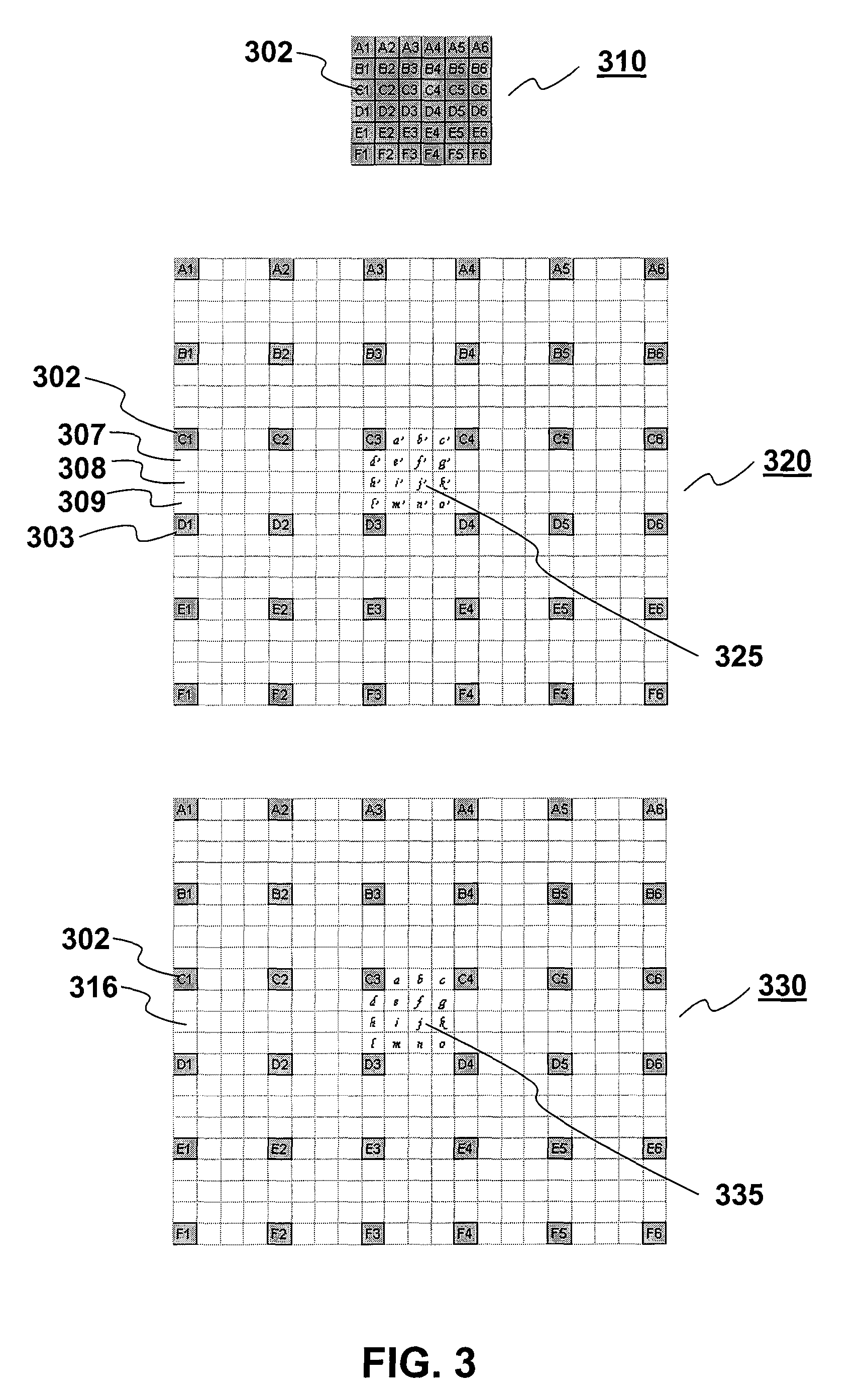
[0007]For motion compensation where much of the data required in coding can be eliminated by comparing the present pixel to the location of the same object in the previous frame, an encoder is used to estimate the motion of object in the image in order to find the corresponding area in a previous frame. If moving objects in a video have non-integer pixel displacement between frames, motion vectors telling the decoder what portion of the previous frame for predicting the new frame will have fractional values instead of integer values. In order to cope with this sort of fractional-pixel motion, it is required to interpolate fractional pixels (hereinafter referred as subpixels) before combining with the residue to reconstitute the current frame.
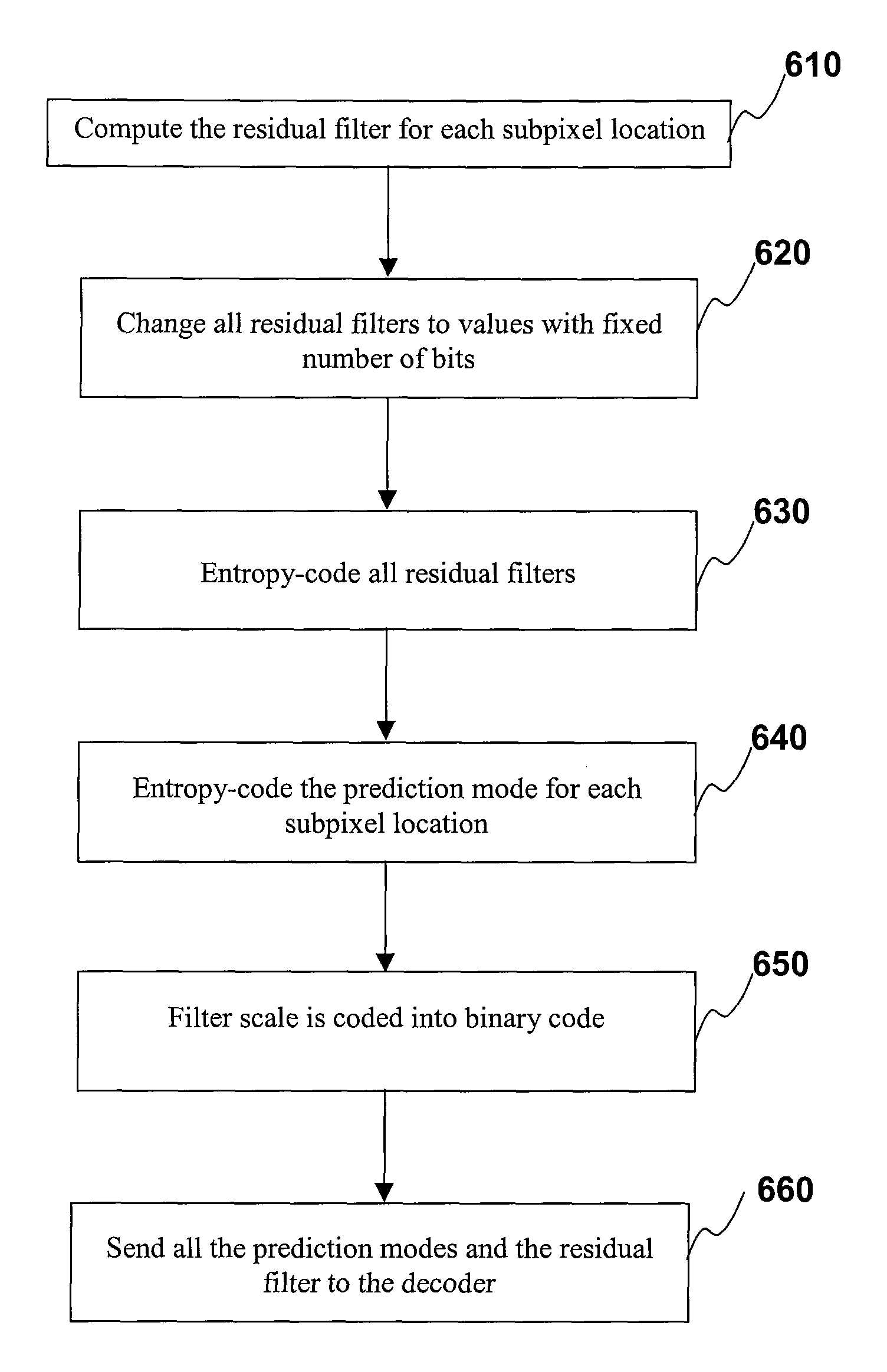
[0009]Therefore, the claimed invention is related to interpolating fractional pixels by using a combination of fixed filter and adaptive filter to generate fractional-pixel images. The filters in use are not restricted to be symmetrical and the sum of the filter coefficient values of the interpolation filter are not fixed which is good for fading video. Fewer multiplications are required in the claimed invention, lowering the complexity of the interpolation with comparable and even better performance in term of video signal quality. The reference pixels used by the disclosed adaptive filter are chosen from a set of subpixels, which are interpolated from a set of fixed filters. Furthermore, the claimed invention provides a coding method adopted by the video encoder for the adaptive filter coefficient in which the adaptive filter coefficients are predicted from standard, upper or left filter such that to reduce the data required to be sent to the video decoder. The disclosed coding of filter coefficients are no longer limited by any predefined filter. A set of disclosed adaptive filter pattern and coefficients can be sent per frame, per field, or per number of macroblocks.

Problems solved by technology

Fixed filters are symmetric and cannot capture any small motion offset between video frames.
For the case of solely using an adaptive filter for interpolation, the complexity will be very high as a lot of costly multiplications are required, for example, each subpixel requires 36 multiplications if 36-tap filter is to interpolate each subpixel from 36 integer pixels.

Method used


Image

  • Method for motion compensation
  • Method for motion compensation
  • Method for motion compensation

Examples


Embodiment Construction

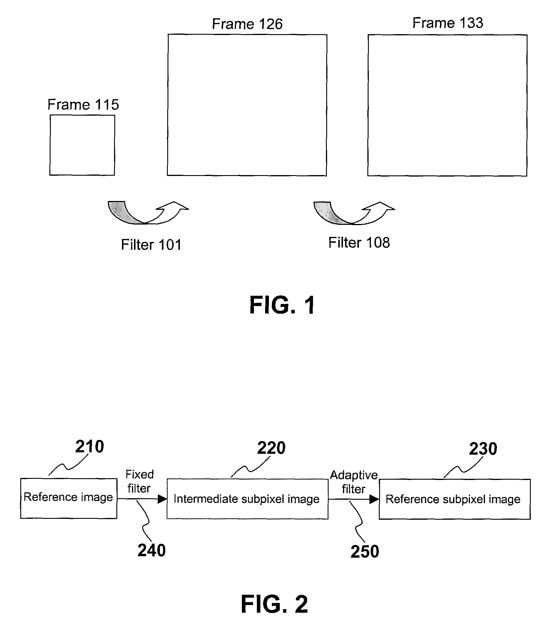
[0019]One embodiment of the claimed invention is to carry out the interpolation of a video frame for motion compensation in two steps as shown in FIG. 1. For interlaced scanning, each image in a video is made up of 2 fields. But for progressive scanning, each image is referred to be a frame. Therefore, these 3 terms: image, field and frame represent a still image in a video—a screenshot at a particular instance and can be used interchangeably throughout this disclosure. As shown in FIG. 1, after passing through filter 101, the resolution of frame 115 will be increased to that of frame 126 up to subpixel level as an intermediate subpixel image. Then frame 126 is further processed by filter 108 to obtain the desired output frame 133 as a reference subpixel image but this time the resolution remains the same as frame 126.

[0020]According to the claimed invention, FIG. 2 further illustrates that in the 2-step filtering process, the first filter in use is a fixed filter 240 and the second...


PUM


Abstract

A method for use in video compression is disclosed. In particular, the claimed invention relates to a method of more efficient fractional-pixel interpolation in two steps by a fixed filter (240) and an adaptive filter (250) for fractional-pixel motion compensation.

Description

RELATED APPLICATION[0001]There are no related applications.TECHNICAL FIELD[0002]The claimed invention relates to a method for video compression. In particular, the claimed invention relates to a method for removing temporal redundancy between video frames by motion compensation.BACKGROUND ART[0003]Video compression addresses the problem of reducing the amount of data required to represent video and a number of standards have been available for implementation. The video coding standards in use today can be grouped into two broad categories according to their intended applications: (i) video teleconferencing standards such as H.261 and H.264 which have been defined by the International Telecommunications Union (ITU) and (ii) multimedia standards such as MPEG-2, MPEG-4 which are developed under the auspices of the Motion Picture Experts Group of the CCITT and ISO.[0004]Despite the existence of a variety of video coding standards, most rely on similar video compression techniques. These...

Claims


Application Information

Patent Timeline
Patent Type & Authority Patents(United States)
IPC IPC(8): H04N7/12
CPCH04N19/105H04N19/176H04N19/61H04N19/523H04N19/14H04N19/82H04N19/117
Inventor WONG, HOI MINGHUO, YAN JENNY
Owner HONG KONG APPLIED SCI & TECH RES INST
Learn More