Remote communications feedback for utility meter

Active Publication Date: 2012-01-17
LANDIS GYR LLC
View PDF10 Cites 2 Cited by
  • Summary
  • Abstract
  • Description
  • Claims
  • Application Information

AI Technical Summary

Benefits of technology

[0012]The above described features and advantages, as well as others, will become more readily apparent to those of ordinary skill in the art by reference to the following detailed description and accompanying drawings. While it would be desirable to provide a utility meter that provides one or more of the above-

Problems solved by technology

When an individual with a local device is attempting to establish a communication session with a meter over the local port, it can be difficult to discern by looking at the annunciator whether the communication session has been established.
Accordingly, when an individual with a local device is at

Method used


Image

  • Remote communications feedback for utility meter
  • Remote communications feedback for utility meter
  • Remote communications feedback for utility meter

Examples


Example

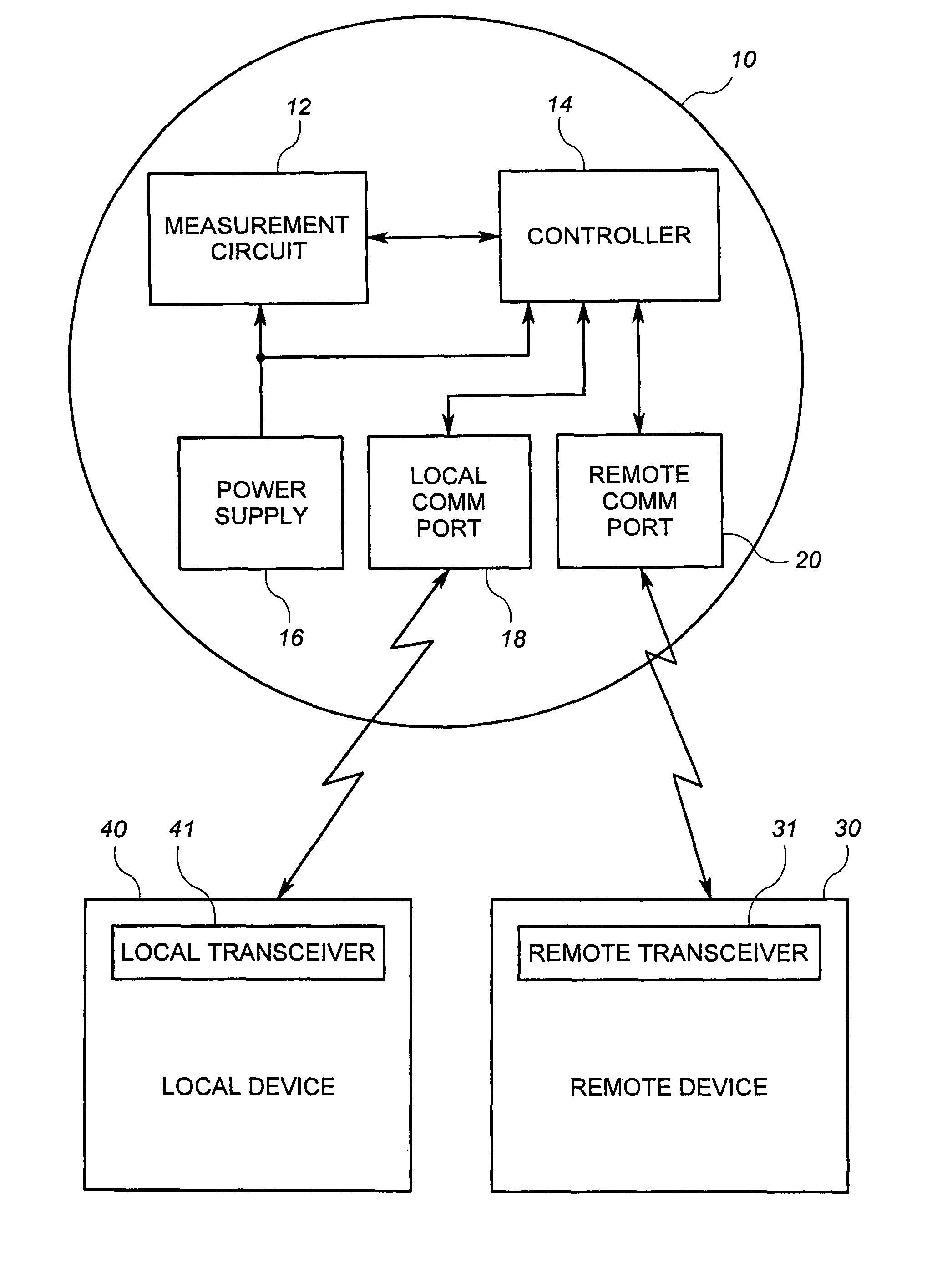
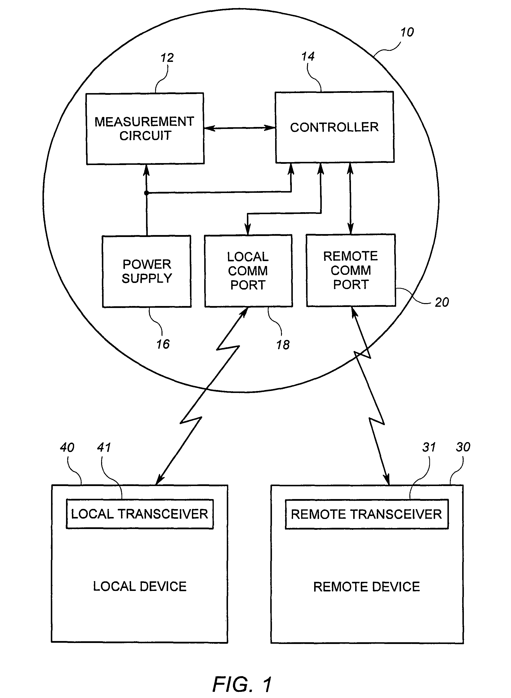
[0023]With reference now to the drawings, FIG. 1 shows an exemplary utility meter 10 in communication with a local device 40 and a remote device 30. In general the local device 40 and the remote device 30 are configured to communicate data to and / or from the utility meter 10.

[0024]The utility meter 10 includes metrology circuitry in the form of a measurement circuit 12, a controller 14 with memory, a power supply 16, a local communications port 18, and a remote communications port 20. It will be appreciated that the utility meter 10 may optionally include other devices such as other communication circuitry, an electronic or mechanical display, and other peripheral devices commonly available in utility meters.

[0025]The exemplary remote device 30 includes a transceiver 31 that is operable to transmit data to or receive data from the utility meter 10. Accordingly, the remote device 30 may transmit and receive data through a wireless transmission, such as an RF transmission. Alternative...


PUM


Abstract

A utility meter comprises a measurement circuit configured to measure consumption, a remote communications port, a local communications port, and a meter communications indicator. The meter communications indicator is configured to provide an indication that the meter is communicating with a remote device external to the meter over the remote communications port. The meter communications indicator is also configured to provide an indication that the meter is communicating with a local device external to the meter over the local communications port. The indication that communications are occurring over the local communications port is different from the indication that communications are occurring over the remote communications port. In at least one embodiment, the communications indicator is configured to provide an indication that communications are occurring simultaneously over the remote communications port and the local communications port.

Description


Claims


Application Information

Patent Timeline
IPC IPC(8): G08C15/06
CPCG01D4/004Y02B90/242Y04S20/322Y02B90/20Y04S20/30
Inventor SCHAMBER, STEVENMORRIS, RICHARDSTENBERG, DAVID ALLEN
Owner LANDIS GYR LLC
Why Eureka
Try Eureka