Scanning image display system and scanning image display

a display system and scanning image technology, applied in the field of scanning image display system and scanning image display, can solve the problems of time to draw one frame, difficult to achieve a large deflection angle as desired, and the scanner is more complicated and difficult to control, so as to prevent dropped frames and flickers, and achieve crisp image

Inactive Publication Date: 2012-01-17
SEIKO EPSON CORP
View PDF6 Cites 7 Cited by
  • Summary
  • Abstract
  • Description
  • Claims
  • Application Information

AI Technical Summary

Benefits of technology

[0014]The invention has an advantage of solving the problems described above, thus providing a scanning image display system and a scanning image display capable of preventing dropped frames and flickers, thereby displaying a crisp image.
[0017]The scanning image display system according to the aspect of the invention heats the plurality of first scan sections with the light in at least a part of the scan period and the reset period of the respective second scan sections. Specifically, for example, by heating the first scan section having shorter imaging time and therefore smaller amount of accumulated heat with the light, the resonant frequency of the first scan section can be lowered. Since the scan rate of each of the first scan sections can be adjusted by thus controlling the resonant frequency of each of the plurality of first scan sections, a crisp image can be displayed on the projection surface while preventing the drop frame and the flicker from occurring.
[0018]Further, since the scanning image display using the laser beam is adopted, there is caused a small variation in wavelength between the laser beams emitted from the light sources of the respective scanning image displays. Thus, even in the case where side-by-side images displayed by the respective scanning image displays, it becomes possible to display a crisp image without creating a noticeable seam between the. Further, since the image is displayed with one laser beam, the luminance variation can be reduced compared to the case of using liquid crystal light valves. Further, since the black level can be set to zero in principle with laser beams, it becomes possible to blend the adjacent edges of the images with good accuracy.

Problems solved by technology

Although a two-dimensional method of scanning a light beam can be used where a single scanner scans in both the horizontal and vertical directions, the resulting scanner is more complicated and difficult to control.
However, one difficultly with using the MEMS mirror, however, is that the MEMS mirror utilizes resonance of the system in order for obtaining a large deflection angle, meaning that if the drive frequency of the MEMS mirror is shifted from the resonant frequency, it is difficult to achieve a large deflection angle as desired.
However, if the heat is accumulated in the MEMS mirror, the resonant frequency of the MEMS mirror is lowered, and if the drive frequency of the MEMS mirror is set lower than a certain level, there is insufficient time to draw one frame and the frame is dropped.
Further, in the scanning image display system adapted to use a plurality of scanning image displays using the MEMS mirrors to perform display by arranging the images formed by the respective scanning image displays, since the plurality of MEMS mirrors operate at respective resonant frequencies, it is difficult to synchronize all the MEMS mirrors of the respective scanning image displays.
Therefore, when a substantial amount of heat is accumulated in the MEMS mirror, dropped frames may result, causing a flicker in the resulting image.

Method used


Image

  • Scanning image display system and scanning image display
  • Scanning image display system and scanning image display
  • Scanning image display system and scanning image display

Examples


first embodiment

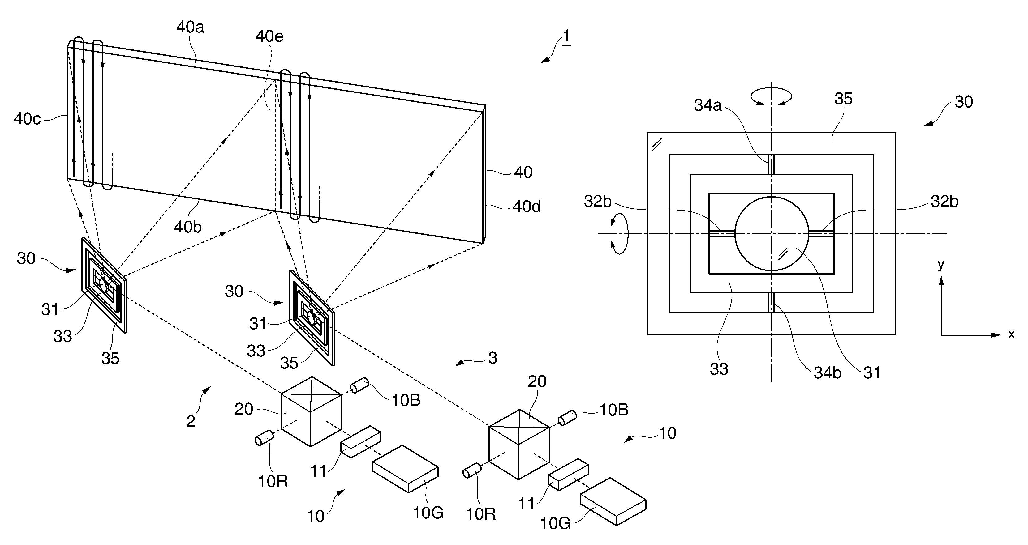
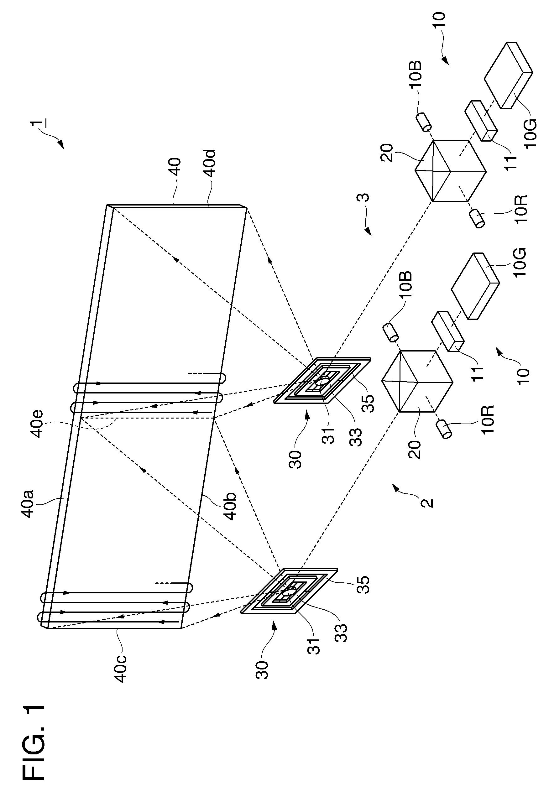
[0030]As shown in FIG. 1, the scanning image display system 1 according to the present embodiment is provided with two scanning image displays 2 and 3. Since the scanning image displays 2 and 3 have the same configuration, the scanning image display 2 will hereinafter be explained.

[0031]The scanning image display 2 is a device provided with a light source 10, a cross dichroic prism 20, and an MEMS mirror 30, and adapted to display an image by scanning a laser beam reflected by the MEMS mirror 30 towards a screen 40.

[0032]The light source 10 is provided with a red light source 10R for emitting a red laser beam, a green light source 10G for emitting a green laser beam, a blue light source10B for emitting a blue laser beam, and an acousto-optic modulator (AOM) 11.

[0033]The red light source 10R is a semiconductor laser (LD) for emitting a red laser beam with a center wavelength of 630 nm, and the blue light source 10B is a semiconductor laser (LD) for emitting a blue laser beam with a c...

second embodiment

[0067]A second embodiment according to the invention will now be explained with reference to FIG. 5. It should be noted that in the drawing of each of the embodiments described hereinafter, portions with configurations common to the scanning image display system 1 as described in the first embodiment above will be denoted with the same reference numerals, and the explanations thereof will be omitted.

[0068]A scanning image display system 50 according to the present embodiment is different from that of the first embodiment in that an auxiliary light source device 60 for heating the MEMS mirror 30 is provided in addition to the light source 10. Otherwise, the scanning image display system 50 is the same as that of the first embodiment in the other configurations.

[0069]As shown in FIG. 5, the auxiliary light source device (another light source) 60 is provided with a light source 61 and a collimator lens 62, and is disposed on the side of the reverse surface (the opposite surface to the ...

third embodiment

[0078]A third embodiment according to the invention will now be explained with reference to FIG. 6.

[0079]A scanning image display system 70 according to the present embodiment is different from that of the first embodiment in the position of an auxiliary light source device 71 and in that the light emitted from the auxiliary light source device 71 is infrared light. The scanning image display system 70 is the same as that of the second embodiment in the other configurations.

[0080]As shown in FIG. 6, the auxiliary light source device 71 is provided with a light emitting diode (LED) 72 for emitting infrared light with a center wavelength of 920 nm, a collimator lens 73, and a dichroic mirror 74.

[0081]The dichroic mirror 74 is for transmitting the light (visible light) emitted from the cross dichroic prism 20, and reflecting the light (invisible light) emitted from the LED 72. The dichroic mirror 74 is disposed on the light path between the cross dichroic prism 20 and the MEMS mirror 3...


PUM


Abstract

A scanning image display system which includes a plurality of scanning image displays each including a light source adapted to emit a laser beam, and a scan unit having a first scan section adapted to scan the laser beam emitted from the light source in a first direction on a projection surface, and a second scan section adapted to scan the laser beam in a second direction substantially perpendicular to the first direction. The first scan sections are resonant scan sections which are faster than the second scan sections in scan speed. The first scan sections are heated with light during the time that an image is formed and a reset period of the second scan sections in order to control resonant frequencies of the first scan sections.

Description

[0001]The entire disclosures of Japanese Patent Application No. 2007-312644, filed Dec. 3, 2007 is expressly incorporated herein by reference.BACKGROUND OF THE INVENTION[0002]1. Technical Field[0003]The present invention relates to a scanning image display system and a scanning image display.[0004]2. Related Art[0005]In recent years, scanning image displays have been adapted so as to display an image by raster-scanning a light beam such as a laser beam on a projection surface.[0006]In order to generate an image using the scanning image display, it is necessary to scan a light beam two-dimensionally using a scanner such as a polygon mirror or a galvanometer mirror. Although a two-dimensional method of scanning a light beam can be used where a single scanner scans in both the horizontal and vertical directions, the resulting scanner is more complicated and difficult to control. Therefore, scanning image displays are typically provided with two sets of scanners, each of which scans alo...

Claims


Application Information

Patent Timeline
Patent Type & Authority Patents(United States)
IPC IPC(8): G02B26/08
CPCH04N9/3129H04N9/3147
Inventor NOJIMA, SHIGEO
Owner SEIKO EPSON CORP
Why Eureka
Try Eureka