
Data support with an optically variable structure

a data support and optical variable technology, applied in office printing, other printing materials, instruments, etc., can solve the problem that the optical variable elements are less suitable for simple visual checks

Active Publication Date: 2012-01-24
GIESECKE & DEVRIENT CURRENCY TECHNOLOGY GMBH
View PDF23 Cites 14 Cited by
  • Summary
  • Abstract
  • Description
  • Claims
  • Application Information

AI Technical Summary

Benefits of technology

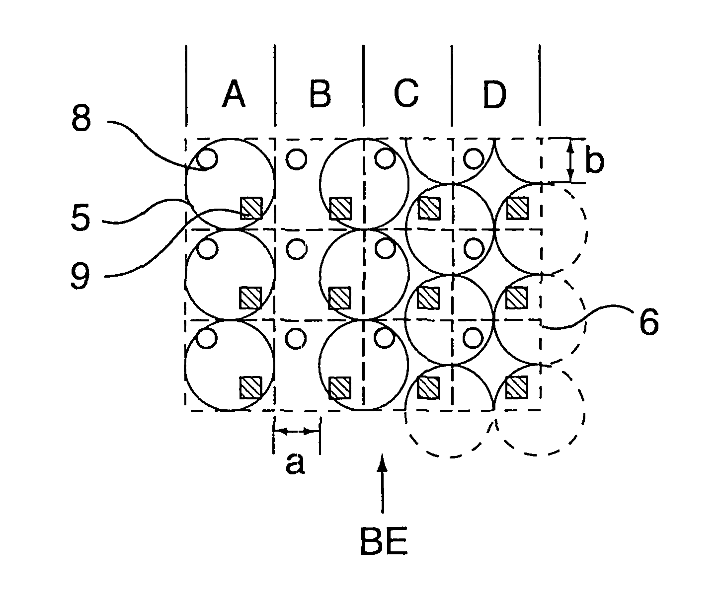
[0007]Moreover, the nonlinear embossed elements according to the invention have the advantage, that in a simple fashion more than two pieces of information can be placed in the optically variable element, which become visible under different viewing angles, since the nonlinear embossed elements have a plurality of flanks, on which the information or parts of the information can be disposed selectively and separate from each other.
[0008]Depending on form, height and dimension of the nonlinear embossed elements, special visual effects can be selectively produced. For example, nonlinear embossed elements in the form of pyramids or frustums of a cone with steeper flanks produce a more contrasting effect when tilted than e.g. nonlinear embossed elements in the form of flattened spherical segments with an equal embossing height.
[0042]The optically variable structure according to the invention or the security element according to the invention preferably is applied onto data carriers, such as for example security documents and documents of value, such as bank notes, share certificates, bond certificates, deeds, vouchers, credit cards or ID cards, passports or the like. In this way the data carriers are provided with a security element which even for laymen is easy recognizable as to increase the forgery-proofness. But the optically variable structure or the security element according to the invention also very advantageously may be used in the area of product protection. Here the optically variable structure or the security element can be applied to respective labels or packaging or directly onto the goods.

Problems solved by technology

The protection from forgery here is based on the fact that the visually simply and distinctly recognizable optically variable effect cannot be reproduced or only insufficiently reproduced by the above-mentioned reproducing devices.
For the visual check of the known optically variable elements, therefore, exactly this viewing angle range must be found, so that these optically variable elements are less suitable for a simple visual check.

Method used


Image

  • Data support with an optically variable structure
  • Data support with an optically variable structure
  • Data support with an optically variable structure

Examples


example 1

FIG. 2 to 13

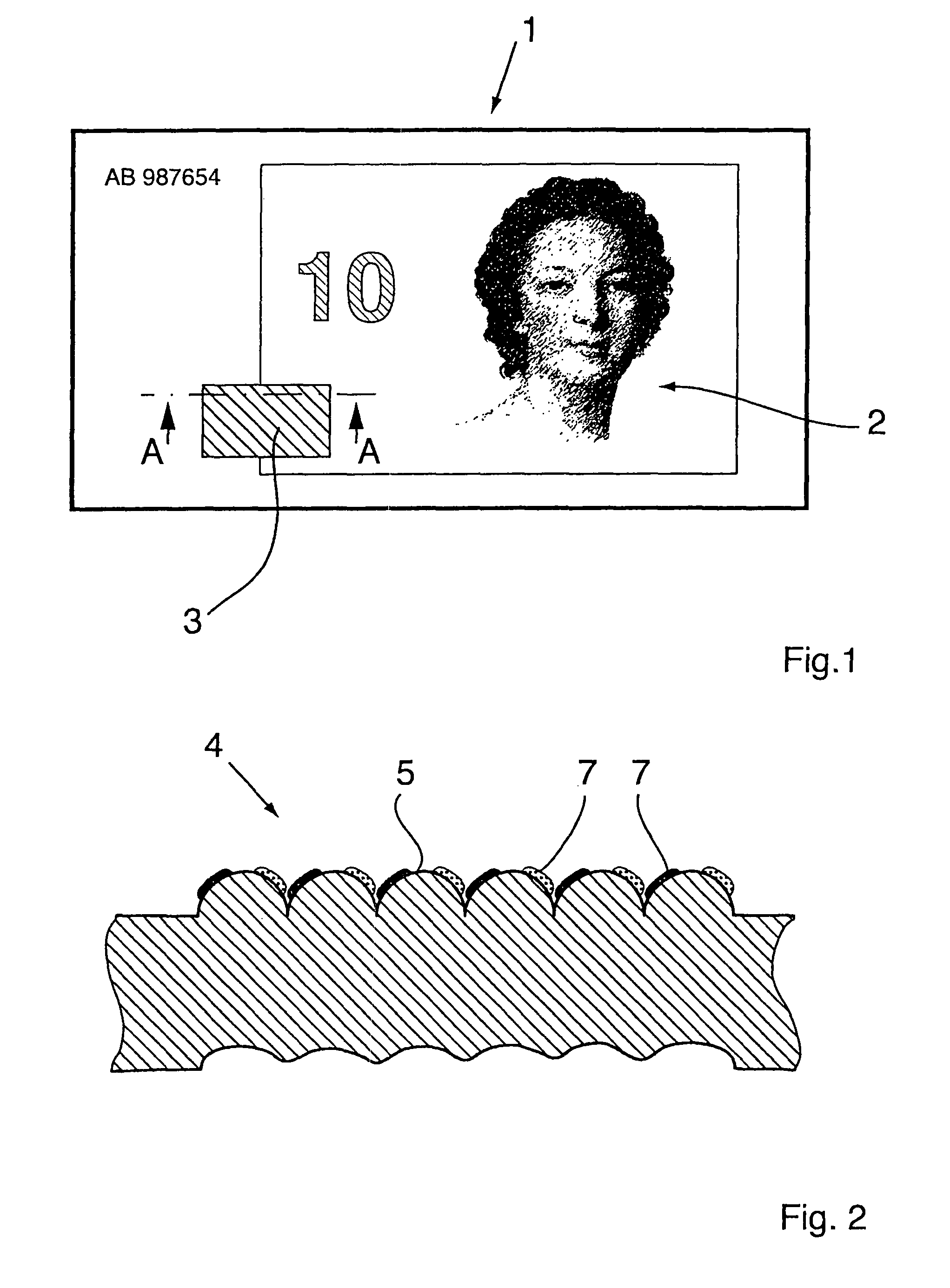
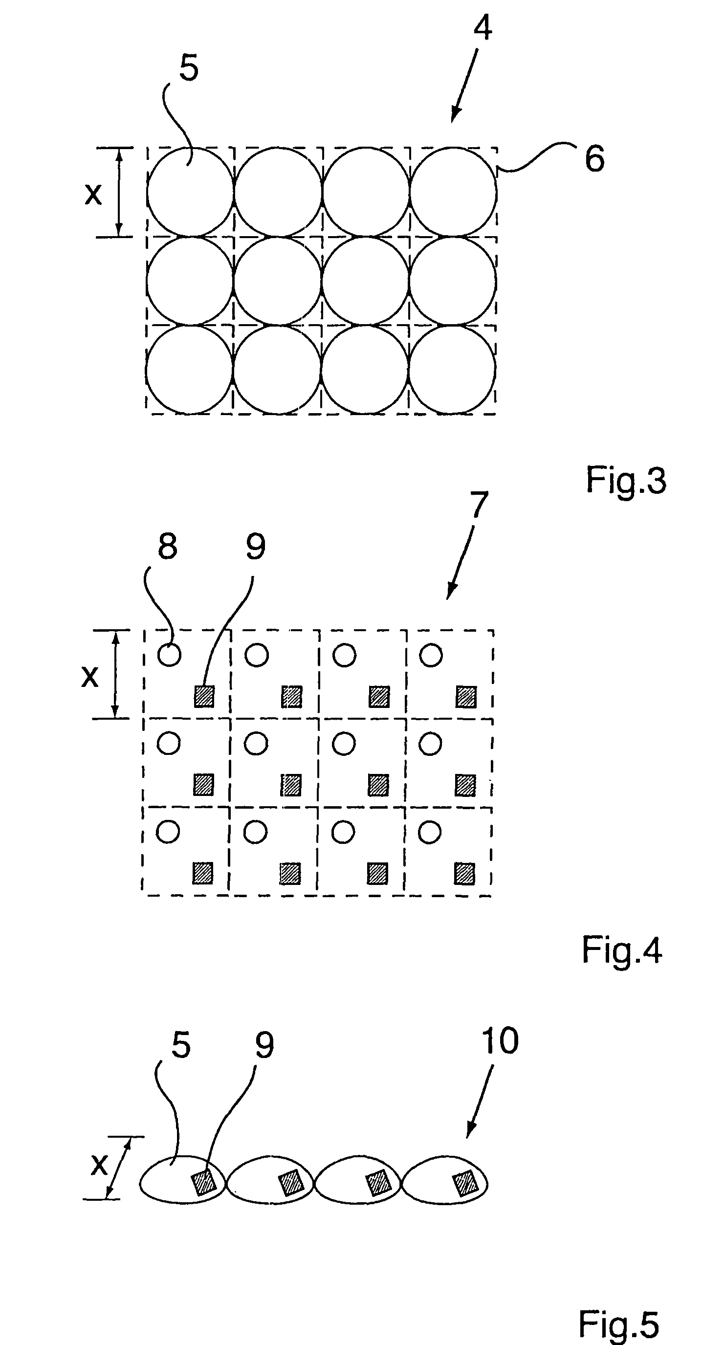
[0114]FIG. 2 schematically shows a sectional view along the line A-A (cf. FIG. 1) and in conjunction with FIGS. 3, 4 and 5 an optically variable structure, wherein the embossed structure 4 is formed by regularly disposed, uniform nonlinear embossed elements 5, i.e. as a periodical screen. The nonlinear embossed elements 5 are provided with a coating 7, which is formed as a multicolored pattern, the individual colored areas of which are located on the flanks of the nonlinear embossed elements.

[0115]That the nonlinear embossed elements 5 are designed as elevations, which preferably are produced by embossing the data carrier, is clearly recognizable at the top side of the data carrier as shown in the sectional view. If the data carrier is mechanically shaped with an embossing tool the bottom side of the data carrier material shows the negative deformation. The deformation here is only schematically represented. The back of the data carrier normally will not have an embossin...

example 2

FIGS. 14, 15 and 16

[0128]FIG. 14 shows another embodiment of the embossed structure 4 according to the invention in top view, wherein the nonlinear embossed elements 11 consist of four-sided pyramids. FIG. 15 in top view shows the pertinent coating 7 according to the invention. It consists of regularly disposed rectangles 12, 13 of different colors. Two differently colored rectangles 12,13 together form a basic pattern element and as such belong to a structural element 10 and are disposed such that they are disposed on opposite flanks of the pyramidal embossed elements 11. FIG. 16 shows the perspective view of a row of structural elements 10, in each of which the rectangle 12 is recognizable.

[0129]Upon perpendicular viewing depending on the dimension of the rectangular areas the viewer again perceives a uniform plane color effect or directly the rectangular areas. When rotating and / or tilting the data carrier again an interplay of colors emerges.

example 3

FIG. 17

[0130]A further variant of the principle according to the invention explained in example 2 is shown in FIG. 17. The optically variable structure 3 has four different images, which each are recognizable when viewed from the viewing directions marked with arrows 1, 2, 3, 4. The pertinent embossed structure as in example 2 consists of four-sided pyramids 11. The coating 7 according to the invention consists of basic pattern elements which have a basically identical structure.

[0131]A basic pattern element is composed of four triangles, wherein in each of the triangles is disposed an image part of one of the four images. The triangle referred to as “1” belongs to the image recognizable under viewing direction 1, the triangle “2” to the image recognizable under viewing direction 2 etc.

[0132]If all image parts are represented in the same color, upon perpendicular viewing no image information whatsoever is recognizable. In the case of a colored embodiment an image information is poss...


PUM


Abstract

The invention relates to a security element with an optically variable structure, which has an embossed structure and a coating, wherein the embossed structure and the coating are combined such that at least parts of the coating are completely visible upon perpendicular viewing, but are concealed upon oblique viewing. This embossed structure has nonlinear embossed elements, which are combined with the coating such that when changing the viewing direction different pieces of information become visible.

Description

FIELD OF THE INVENTION[0001]The invention relates to a data carrier with an optically variable structure, which has an embossed structure and a coating contrasting to the surface of the data carrier, wherein the embossed structure and the coating are combined such that at least parts of the coating are completely visible upon perpendicular viewing, but are concealed upon oblique viewing and when viewed from at least one predetermined viewing angle a first information is recognizable, which upon perpendicular viewing is not visible or only faintly visible.BACKGROUND[0002]For protection against imitation, in particular with color copying machines or other reproducing methods, data carriers, such as for example bank notes, papers of value, credit or ID cards, passports, deeds and the like, labels, packaging or other elements for the product protection, are equipped with optically variable security elements. The protection from forgery here is based on the fact that the visually simply ...

Claims


Application Information

Patent Timeline
IPC IPC(8): B42D15/00B42D15/10
CPCG07D7/0006B42D2033/24B42D25/41B42D25/324B42D25/378B42D25/373G07D7/003B42D25/425
Inventor HEINE, ASTRIDADAMCZYK, ROGERBALDUS, CHRISTOFMAYER, KARLHEINZFRANZ, PETER
Owner GIESECKE & DEVRIENT CURRENCY TECHNOLOGY GMBH
Learn More