Method of machining airfoil root fillets

a technology of airfoil and root fillet, which is applied in the direction of propellers, propulsive elements, water-acting propulsive elements, etc., can solve the problems of limited fillet radius, high steady state and vibration stress on gas turbine engine airfoils, and the design of the fillet is farther limited

Active Publication Date: 2012-01-24
PRATT & WHITNEY CANADA CORP
View PDF12 Cites 17 Cited by
  • Summary
  • Abstract
  • Description
  • Claims
  • Application Information

AI Technical Summary

Problems solved by technology

Gas turbine engine airfoils are subject to high steady state and vibration stresses during use.
However, the radius of the fillets is limited by 1) the impact it might have of the flow performance of the working fluid being acted upon by the airfoils and 2) by the airfoil resonant frequency criteria.
The design of the fillet is farther limited by the manufacturing constraints.

Method used


Image

  • Method of machining airfoil root fillets
  • Method of machining airfoil root fillets
  • Method of machining airfoil root fillets

Examples


Embodiment Construction

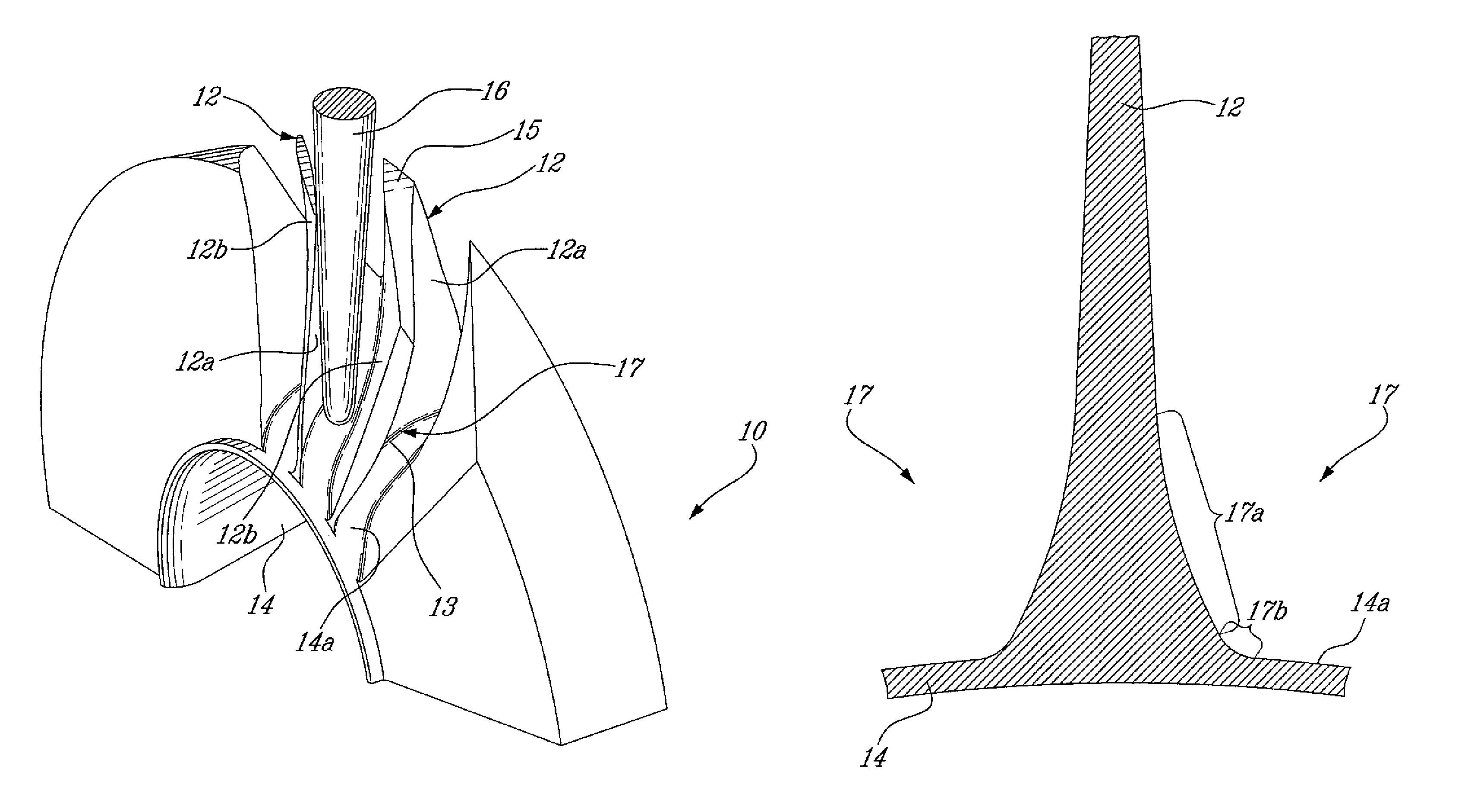
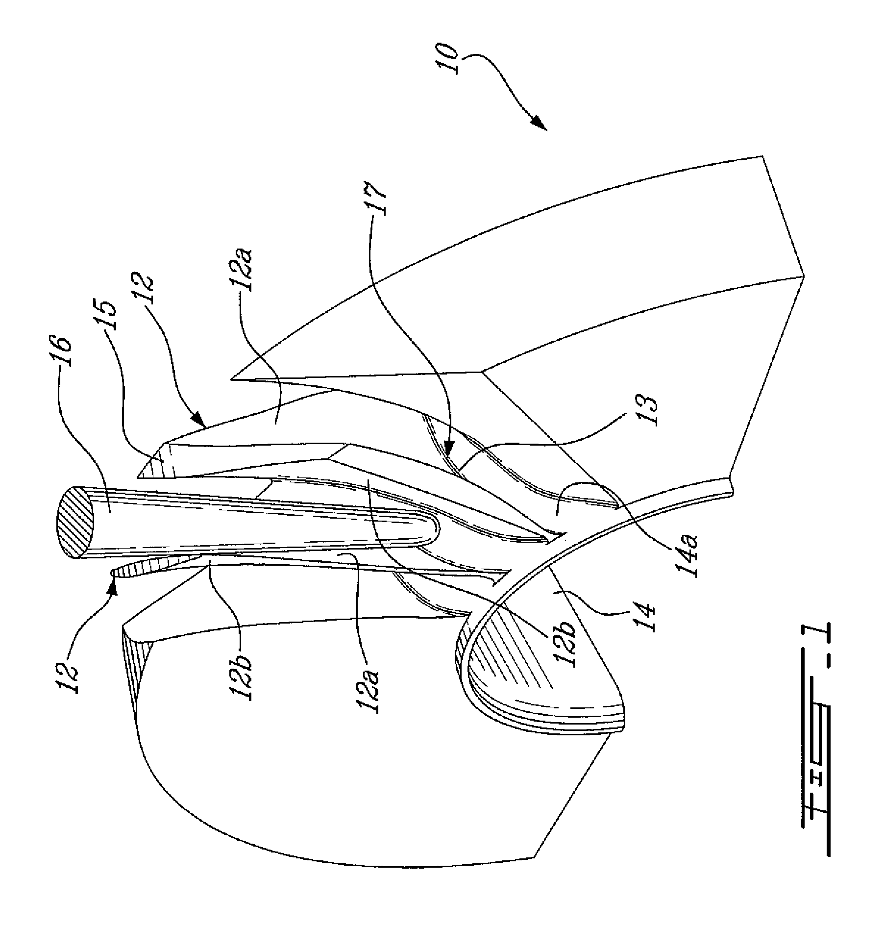
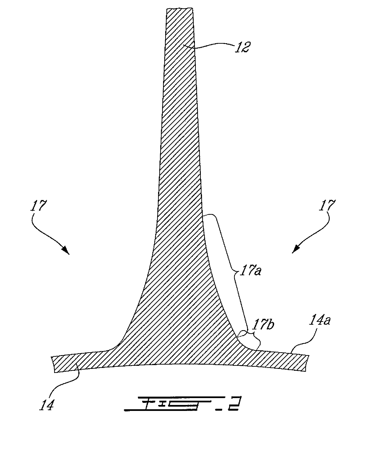
[0014]FIG. 1 illustrates an integrated bladed rotor (IBR) 10 in the process of being machined. IBRs are also known as bladed discs (blisks) and generally comprise a plurality of integral airfoils 12 extending radially outwardly from a hub 14. Such IBRs are typically mounted in the compressor section of gas turbine engines for rotation about the central axis of the engines. The rotation of the IBR 10 imparts energy to the incoming air which is first accelerated and then diffused for recovering of energy to compress the air. The radially outer surface of the hub 14 provides a radially inner flowpath surface 14a for the air flowing axially through the IBR 10. Each airfoil 12 has a concave airfoil pressure side 12a and an opposite convex airfoil suction side 12b extending radially from a root 13 to a tip 15. A root fillet 17 (as best shown in FIG. 2) extends circumferentially completely around each airfoil 12 between the airfoil 12 and the flowpath surface 14a of the hub 14. As will be ...


PUM

PropertyMeasurementUnit
stress concentrationaaaaaaaaaa

Abstract

An airfoil root fillet having a predetermined compound curve profile can be flank milled with a single flank milling cutter having a generally conical flank milling portion and a rounded tip portion defining a compound curve.

Description

TECHNICAL FIELD[0001]The application relates generally to gas turbine engines and, more particularly, to the design and machining of airfoil root fillets with complex curve geometry.BACKGROUND OF THE ART[0002]Gas turbine engine airfoils are subject to high steady state and vibration stresses during use. The resulting mechanical stresses tend to be particularly important at the root of the airfoils that is at the juncture between the airfoils and the associated supporting structure. Fillets have been used at the junction between the airfoils and the supporting structure to reduce stress concentration. Generally, the larger the fillet radius, the lower the stress concentration is. However, the radius of the fillets is limited by 1) the impact it might have of the flow performance of the working fluid being acted upon by the airfoils and 2) by the airfoil resonant frequency criteria. The design of the fillet is farther limited by the manufacturing constraints.[0003]Accordingly, there i...

Claims


Application Information

Patent Timeline
Patent Type & Authority Patents(United States)
IPC IPC(8): F01D11/00
CPCB23C3/18B23C5/1009F01D5/34B23C2215/44Y10T409/303752Y10T29/4932Y10T409/303808Y10T29/49336Y10T409/303416
Inventor STONE, PAULCHAWLA, DINESHKELLY, FRANKFAZARI, EDWARDHEIKURINEN, KARITHERATIL, IGNATIUS
Owner PRATT & WHITNEY CANADA CORP
Why Eureka
Try Eureka