Image forming apparatus with contact/separation mechanism to/from intermediate transfer body

a technology of contact/separation mechanism and image forming apparatus, which is applied in the direction of electrographic process apparatus, instruments, optics, etc., can solve the problems of reducing cost, and achieve the effect of efficient confirmation of operation

Inactive Publication Date: 2012-01-31
KONICA MINOLTA BUSINESS TECH INC
View PDF10 Cites 5 Cited by
  • Summary
  • Abstract
  • Description
  • Claims
  • Application Information

AI Technical Summary

Benefits of technology

[0015]The present invention was made in view of the foregoing and it object is to provide an image forming apparatus including a contact / separation mechanism to / from the intermediate transfer body capable of efficiently confirming operation of the contact / separation mechanism by detecting presence / absence of a patch image formed on the intermediate transfer body using a density sensor, and to provide a method of confirming operation of contact / separation mechanism in the image forming apparatus.
[0020]By the present invention, in an image forming apparatus having a contact / separation mechanism to / from an intermediate transfer body, it becomes possible to efficiently confirm the operation of contact / separation mechanism by detecting density of a toner image formed on the intermediate transfer body by the density detecting unit, without using any sensor for detecting contact / separation.

Problems solved by technology

Further, based on the sensor signal, it detects abnormality of contact / separation of the belt cleaner with respect to the control, and detects any error of the cleaner contact / separation mechanism.
The sensor mentioned above, however, is one of the factors hindering cost reduction.

Method used


Image

  • Image forming apparatus with contact/separation mechanism to/from intermediate transfer body
  • Image forming apparatus with contact/separation mechanism to/from intermediate transfer body
  • Image forming apparatus with contact/separation mechanism to/from intermediate transfer body

Examples


first embodiment

Modification of First Embodiment

[0083]In the example described above, the determination process is performed at the timing of starting / recovering operation, for example, when the power is turned on, or when a body cover, not shown, is closed. The process, however, may be performed at other timings. For example, the process may be performed when a print instruction is input through an input key 111b, when standby period of printing process exceeds a prescribed time period, or when the printing process ends.

Second Embodiment

[0084]As a second embodiment of the present invention, a tandem type color printer as an image forming apparatus will be described. It is assumed that internal configuration of printer 100B in accordance with the second embodiment is the same as that of printer 100A in accordance with the first embodiment shown in FIG. 8.

[0085]In FIG. 12, portions similar to those of printer 100A are denoted by the same reference characters. Referring to FIG. 12, approximately at t...

second embodiment

Modification of Second Embodiment

[0123]In the example described above, the determination process is performed at the timing of starting / recovering operation, for example, when the power is turned on, or when a body cover, not shown, is closed. The process, however, may be performed at other timings. For example, the process may be performed when a print instruction is input through an input key 111b, when standby period of printing process exceeds a prescribed time period, or when the printing process ends.

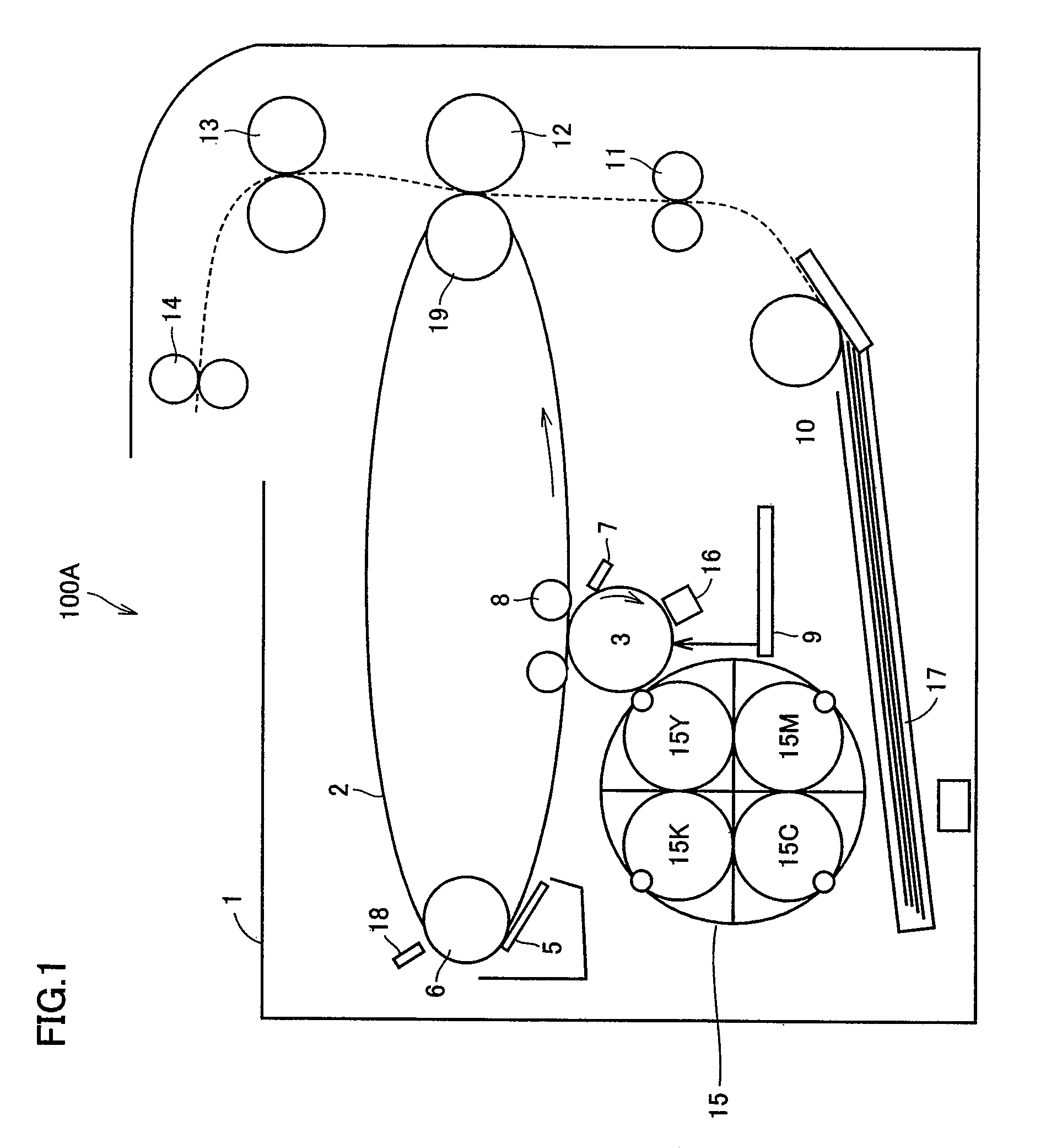
[0124]In printer 100B, whether the transfer roller contact / separation mechanism operates normally / abnormally is determined by CPU 120 based on the detection signal from density sensor 18, through the determination process described above. If the printer 100B has a cleaner contact / separation mechanism and cleaner blade 51 is brought into contact with / separated from intermediate transfer belt 2 by the operation of cleaner belt 5, the determination process for determining whether the...


PUM


Abstract

In a printer, three toner patches are primary-transferred successively to an intermediate transfer belt. Here, after the first toner patch passes through a belt cleaner and before the second toner patch reaches the belt cleaner, and after the second toner patch passes through the belt cleaner and before the third patch reaches the belt cleaner, the belt cleaner is operated to change the state of contact to the intermediate transfer belt to a different state. A density sensor detects density of the toner image on the intermediate transfer belt, and presence / absence of the toner patch is detected. When presence / absence of the first to third patches is detected alternately, it is determined that the belt cleaner is performing the operation described above.

Description

[0001]This application is based on Japanese Patent Application No. 2008-068157 filed with the Japan Patent Office on Mar. 17, 2008, the entire content of which is hereby incorporated by reference.BACKGROUND OF THE INVENTION[0002]1. Field of the Invention[0003]The present invention relates to an image forming apparatus including a contact / separation mechanism to / from an intermediate transfer body, and to a method of confirming an operation of the contact / separation mechanism in the image forming apparatus.[0004]2. Description of the Related Art[0005]In a four-cycle color printer as a conventional image forming apparatus performing color printing, an intermediate transfer belt as an intermediate transfer body is rotated four times to form a color image on the intermediate transfer belt. Specifically, toner images of yellow (Y), magenta (M), cyan (C) and black (K) are formed superposed on the intermediate transfer belt, and transferred to a sheet of paper, so that a color image is prin...

Claims


Application Information

Patent Timeline
Patent Type & Authority Patents(United States)
IPC IPC(8): G03G15/16
CPCG03G15/161G03G15/0173G03G15/5058G03G2215/00059
Inventor NOZAWA, SHIGEKIFURUBAYASHI, TOSHIYAMARUYAMA, YOSHINORIHONDA, TAKASHIKONDO, MASAO
Owner KONICA MINOLTA BUSINESS TECH INC
Why Eureka
Try Eureka