
Twin clutch speed-change apparatus

a technology of speed-change apparatus and clutch, which is applied in the direction of mechanical actuated clutches, interengaging clutches, gearing, etc., can solve the problems of shifting sound and/or shock, and achieve the effect of reducing shifting shock

Active Publication Date: 2012-02-07
HONDA MOTOR CO LTD
View PDF12 Cites 14 Cited by
  • Summary
  • Abstract
  • Description
  • Claims
  • Application Information

AI Technical Summary

Benefits of technology

This configuration effectively reduces shift shock and slapping sounds by minimizing the rotational backlash and increasing the ease of engagement of the dog clutch, while maintaining a lightweight design by avoiding unnecessary wasted portions between adjacent dog teeth.

Problems solved by technology

There is a possibility that a flapping sound and / or shock may occur at that time.

Method used


Image

  • Twin clutch speed-change apparatus
  • Twin clutch speed-change apparatus
  • Twin clutch speed-change apparatus

Examples


Embodiment Construction

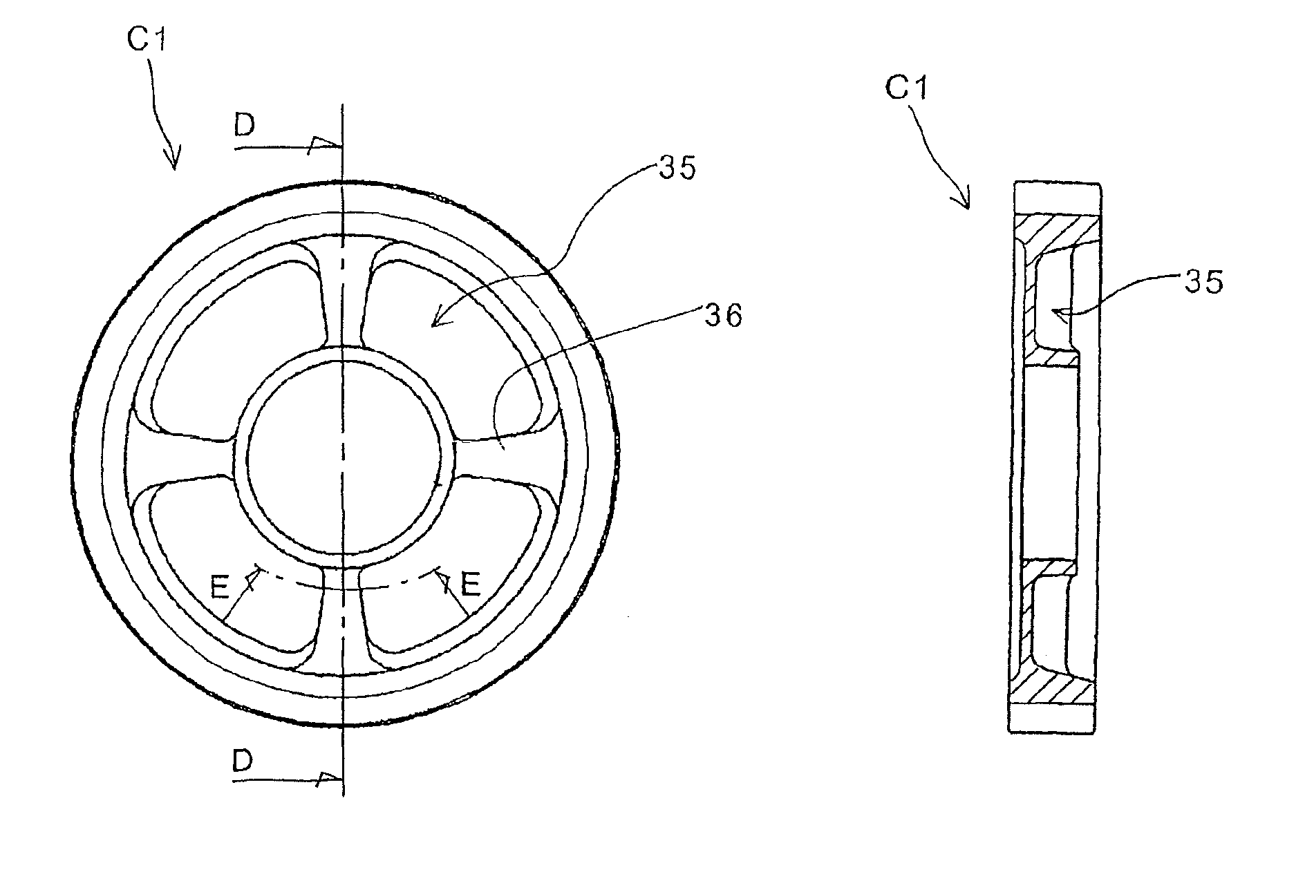
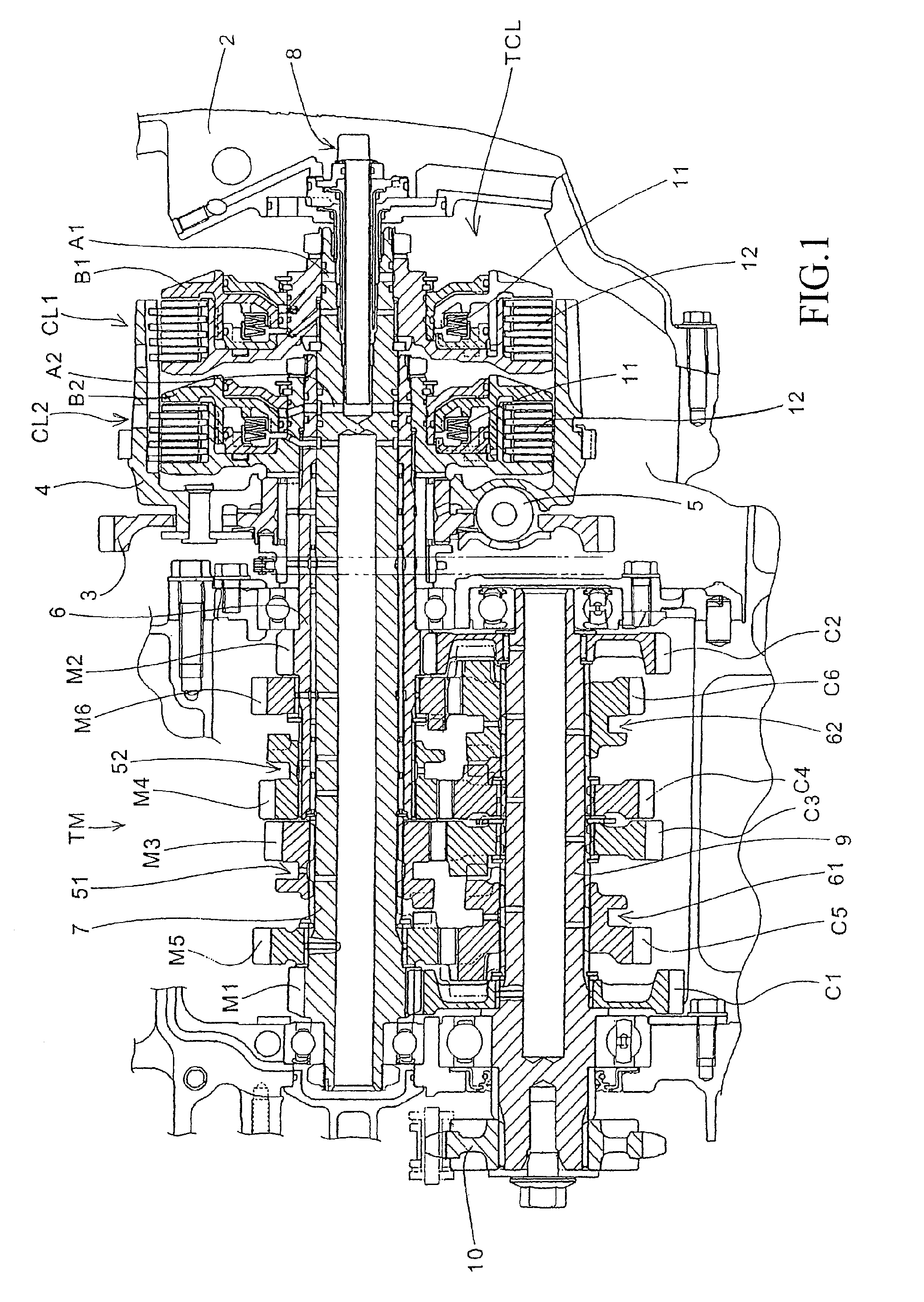
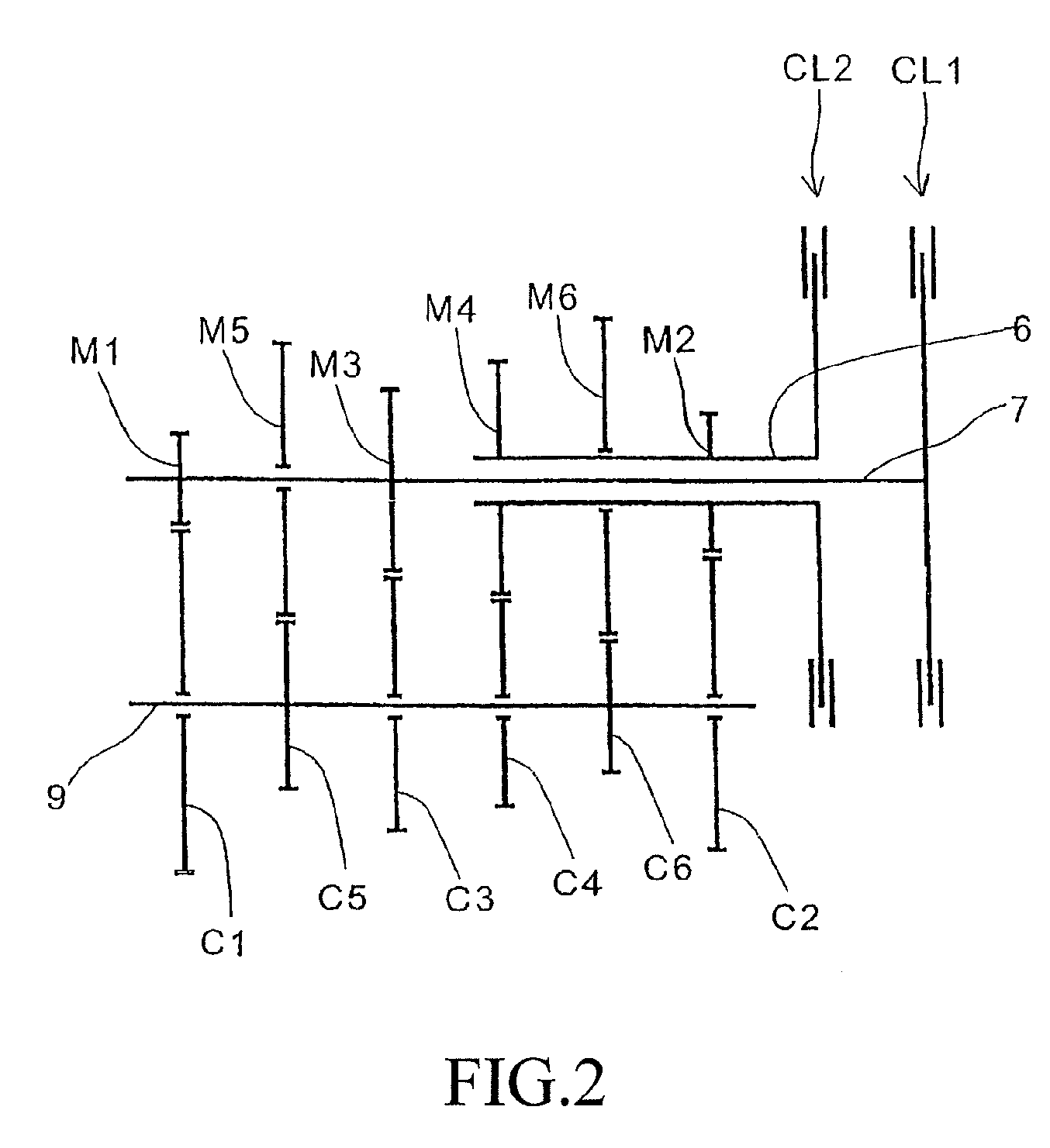
[0033]FIG. 1 is a cross-sectional view of a twin clutch type speed-change apparatus 1 according to an embodiment of the present invention. FIG. 2 is a skeleton diagram illustrating speed-change gear arrangement of the speed-change apparatus 1. The twin clutch speed-change apparatus includes a twin clutch TCL composed of a first clutch CL1 and a second clutch CL2, and a six-forward-speed sequential transmission TM. The speed-change apparatus is accommodated inside a crankcase 2 together with an engine (not shown) as a power source of a vehicle.

[0034]A rotational drive power is transmitted from a crankshaft (not shown) of the engine to a primary gear 3 having a shock absorbing mechanism 5. The rotational drive power is outputted therefrom to a countershaft 9 attached with a drive sprocket 10 through the twin clutch TCL, an outer main shaft 6 as an external tube, an inner main shaft 7 as an inner tube rotatably carried by the outer tube, and six gear pairs provided between the main sha...


PUM


Abstract

A twin clutch speed-change apparatus that can reduce shift shock includes a transmission with multiple gear pairs disposed between a main shaft and a countershaft. A twin clutch is provided on the main shaft, a rotational drive force from an engine being connected / disconnected between the transmission and the engine, a dog clutch is provided between an axially slidably attached slidable gear and an axially non-slidably attached non-slidable gear to select a gear pair, for transmitting a rotational drive force, from the multiple gear pairs. Dog teeth of the dog clutch include steps different in axial height from each other between a portion abutted against a lateral wall surface of a dog hole when the rotational drive force is transmitted by the dog clutch, and a portion abutted against a lateral wall surface of the dog hole when the rotational drive force is not transmitted by the dog clutch.

Description

CROSS-REFERENCE TO RELATED APPLICATION[0001]The present application claims priority under 35 U.S.C. §119 to Japanese Patent Application No. 2007-255125, filed Sep. 28, 2007, the entire contents of which are hereby incorporated by reference.BACKGROUND OF THE INVENTION[0002]1. Field of the Invention[0003]The present invention relates to twin clutch type speed-change apparatuses and, in particular, to a twin clutch type speed-change apparatus that reduces shift shock by providing a step on dog teeth provided on a speed-change gear sliding on a shaft.[0004]2. Description of Background Art[0005]Japanese Patent Laid-Open No. 2007-100739 discloses a multi-step transmission having a plurality of speed-change gear pairs configured such that shifting operation is executed by allowing shift forks parallel sliding on a main shaft and a countershaft to drive speed-change gears and sleeves slidable on the main shaft and the countershaft.[0006]In particular, this document discloses a twin clutch t...

Claims


Application Information

Patent Timeline
Patent Type & Authority Patents(United States)
IPC IPC(8): F16H3/08F16H3/089
CPCF16D11/10F16H3/006F16D2011/008F16H3/16F16H63/30F16H2063/3093Y10T74/19228Y10T74/19288Y10T74/19372Y10T74/19358Y10T74/19242F16H57/028F16H61/04F16H3/091
Inventor TSUKADA, YOSHIAKIOZEKI, TAKASHIKOJIMA, HIROYUKINEDACHI, YOSHIAKISUGITA, HARUOMI
Owner HONDA MOTOR CO LTD
Learn More