Medical tube and system for locating the same in a body using passive integrated transponders

a technology of medical tubes and integrated transponders, which is applied in the field of medical tubes, can solve the problems of inconvenient and costly patient care, inability to detect the location of medical tubes in the patient's lungs, and inability to provide feeding solution,

Active Publication Date: 2012-02-14
HEALTH BEACONS
View PDF11 Cites 18 Cited by
  • Summary
  • Abstract
  • Description
  • Claims
  • Application Information

AI Technical Summary

Benefits of technology

[0027]Due to the sensitivity of the grid dip detection apparatus to the transponder's field strength gradient, additional imaging equipment is not necessary to detect the location of the medical tube. Accordingly, the present invention is suitable for use in environments which lack such equipment. For example, ambulances and nursing homes rarely have X-ray equipment on-site, and the apparatus and method of the invention are particularly suited for use in such facilities and situations. A major advantage of the invention is that the method and apparatus can routinely be used at a bedside, for easy efficient and inexpensive ongoing bedside monitoring without radiation.
[0028]Referring to FIG. 1, a nasogastric tube 30 having a permanent passive integrated transponder 20 at or adjacent its distal end is illustrated inserted in a body. In a preferred embodiment, a grid dip meter sensor 10 measures the amount of electromagnetic energy from the passive integrated transponder 20 attached to the medical tube 30. A grid dip meter is an oscillator whose output energy changes in the vicinity of a circuit which is in resonance with the frequency the oscillator generates, somewhat similar to an acoustic tone becoming louder when generated in the vicinity of a resonant cavity. When the detection apparatus is brought in proximity to the passive integrated transponder, the sensed value of the transponders electromagnetic field is displayed by a reading device 40, integrated with the sensor 10. In the preferred embodiment the PIT tag attached to the medical tube operates in a frequency range of 1 KHz to 5.4 GHz with 120 to 135 KHz being the preferred range.
[0029]Referring to FIG. 2, the reading device 40 visually displays a representation of the passive integrated transponder's electromagnetic field strength gradient. Such a representation can be made with a light-emitting diode bar array or a liquid crystal display. In addition, a speaker 50 may optionally but preferably be employed. A tone generator receives the electromagnetic signal and provides a tone signal to the speaker. The tone signal is proportional to the magnitude of the electromagnetic signal of the PIT device. The sound projected by the speaker may change in volume or pitch corresponding to the magnitude of the PIT signal. Such a visual display 40 and / or speaker 50 allows the user to move or sweep the detection apparatus over the patient's body and to quickly determine the nearest external point to the location of the internal passive integrated transponder 20 associated with the medical tube.
[0030]Referring to FIG. 3 in a further embodiment with respect to a feeding tube 60, a passive integrated transponder 70 may be incorporated into the tip of the tube 60. The small size of the passive integrated transponder helps the tube be passed and advanced down the trachea and esophagus and into the stomach. In this embodiment, the size of the passive integrated transponder should not exceed about 15 mm in diameter, with 6 to 12 being preferred, so that it can be passed into the stomach via either the nose or mouth. Once in place, the location of the passive integrated transponder, and thus the end of the feeding tube, can be determined by the reading apparatus of the invention (FIG. 2).
[0031]Referring to FIG. 4, in a further embodiment of the invention, an endotrachael tube 80 is provided with a plurality of passive integrated transponders 90 spaced from one another along the longitudinal axis of the tube. In this example, multiple PIT elements 90 are used to provide a range of detection sites to identify and bracket a specific locale in the trachea and / or to provide for more precise location of the tube and / or as a safe-guard in the event the magnetic field of one of the PIT elements is weak, disrupted or undetectable.
[0032]As the sensor 10 is scanned over the length of a transponder 20, the transponder returns to the sensor a peak signal at each end (the magnetic poles of the electromagnetic field) of the transponder and a relatively minor signal when the scanner is aligned with the mid-portion of the transponder. The peak signals thus bracket the location of each transponder in the body, e.g., in the trachea.

Problems solved by technology

If the end of the feeding tube is not properly positioned within the stomach, aspiration of the feeding solution into the patient's lungs may occur.
This is both inconvenient and costly to the patient, and is particularly stressful in those instances where the patient repeatedly and inadvertently removes a medical tube, such as a feeding tube, thus requiring repeated reinsertion and X-rays.
Prior attempts at detecting the location of medical tubes within a patient have met with only limited success.
An external power source adds significant risk associated with shock or electrocution, and requires that electrical connections be made prior to positioning of the catheter within the patient.
An internal power source, such as a battery, must be relatively small and can only provide power to the transmitter for a limited time.
This precludes long-term detection of the catheter's location, and poses additional risks associated with placing a battery internally in a patient, such as the risk of battery leakage or rupture.
In addition, the transmitter is relatively complex, and requires an active electronic circuit (either internal or external to the catheter), as well as the various wires and connections necessary for its proper function.
Because of this, the forces between the small magnet and the magnetized compass pointer at distances greater than several centimeters are not strong enough to accurately orient the compass towards the small magnet.

Method used


Image

  • Medical tube and system for locating the same in a body using passive integrated transponders
  • Medical tube and system for locating the same in a body using passive integrated transponders
  • Medical tube and system for locating the same in a body using passive integrated transponders

Examples


example 1

Detection of a Feeding Tube

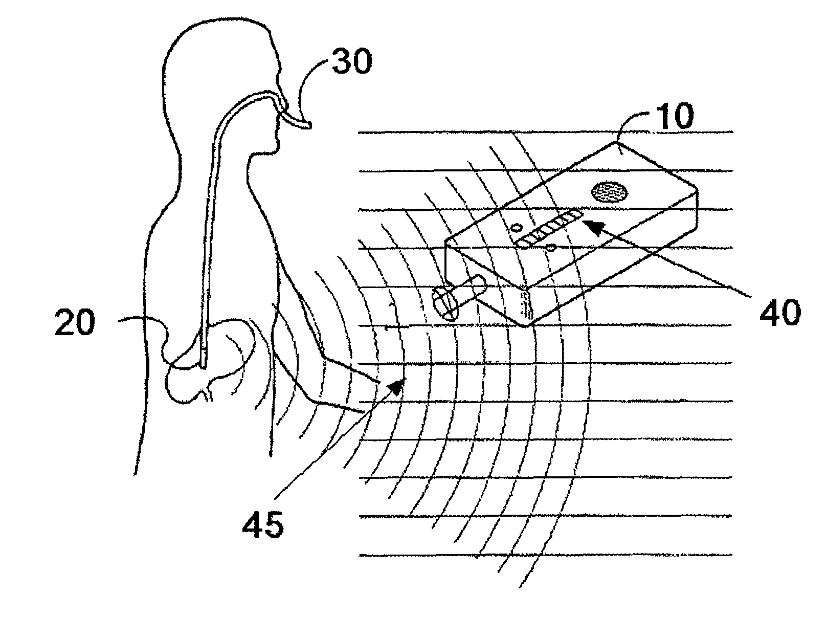
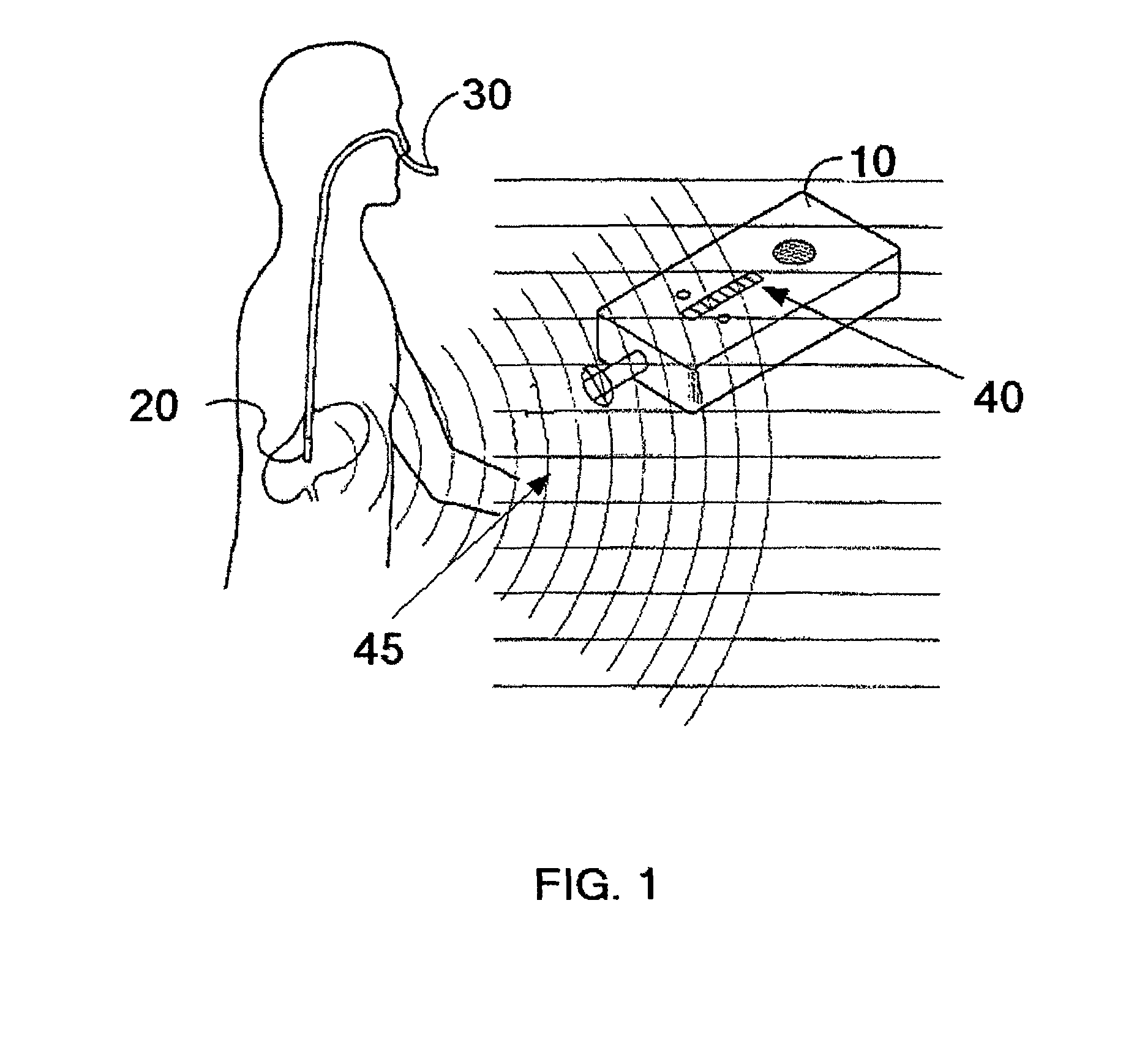
[0039]The feeding tube 30 shown in FIG. 1 is inserted into a patient's nose, down the esophagus and into the stomach. The detection apparatus (10) is employed to sense the passive integrated transponder's field strength. As the detection apparatus 10 is scanned about the patient's body, greater and lesser electromagnetic field gradients 45 are indicated. The closer to the PIT tag is to the grid dip oscillator detection device the greater is the reader signal. The feeding tube 30 is located by moving the detection apparatus until the greatest magnitude is indicated by the detection apparatus visual display and / or speaker sound volume or pitch.

example 2

Detection of an Endotracheal Tube with Multiple PIT Tags

[0040]The endotrachael tube 80 shown in FIG. 4 is inserted into the patient's mouth and into the airway to the lungs. The multiple PIT tags (90) are used in order to allow a range of detection sites so as to bracket the precise location in the patient. This method allows more precise detection of the tube in the event the electromagnetic field of any one tag is disrupted or undetectable.


PUM


Abstract

A medical tube has one or more permanent passive integrated transponders associated therewith that are capable of being located by a detection apparatus which senses the electromagnetic field strength gradient generated by each passive integrated transponder associated with the medical tube and indicates the value of the gradient to the user. In one embodiment, the passive integrated transponder is associated with the distal end of an endotracheal medical tube in a fixed orientation with an electromagnetic field pointing at a preferred angle of no more than 15 degrees to the longitudinal axis of the medical tube. The passive integrated transponder's static electromagnetic field is sensed by the detection apparatus and indicates the location of the distal end of the medical tube within a body.

Description

CROSS-REFERENCE[0001]This application claims the benefit of U.S. Provisional Applications No. 60 / 849,825, filed Oct. 6, 2006, and No. 60 / 850,391, filed Oct. 10, 2006.FIELD OF THE INVENTION[0002]This invention is generally directed to a medical tube, for example, an endotracheal tube or a nasogastric tube, and a detection system and method for ascertaining the location of the medical tube within a body, and, more specifically, to a medical tube capable of being located using a detection apparatus which senses a static electromagnetic field strength gradient generated by one or more passive integrated transponders associated with the medical tube.BACKGROUND OF THE INVENTION[0003]There are many instances in clinical medicine where detecting the location of a medical tube within a patient is important. For example, when positioning feeding tubes through the mouth or nose of a patient, it is essential that the end of the feeding tube pass into the patient's stomach, and that it does not ...

Claims


Application Information

Patent Timeline
Patent Type & Authority Patents(United States)
IPC IPC(8): A61B19/00
CPCA61B5/06A61B5/062
Inventor PETCAVICH, ROBERT J.REICHER, MURRAY
Owner HEALTH BEACONS
Why Eureka
Try Eureka