
Straight line type air compressor

An air compressor, linear technology, applied in the field of air compressors, can solve the problems of complex overall structure, low transmission efficiency, and large volume of air compressors, and achieve the effects of light weight, improved efficiency, and simple maintenance.

Inactive Publication Date: 2008-10-29
ZHEJIANG UNIV
View PDF0 Cites 8 Cited by
  • Summary
  • Abstract
  • Description
  • Claims
  • Application Information

AI Technical Summary

Problems solved by technology

[0006] In summary, the overall structure of the air compressor with this structure is complex, bulky, low transmission efficiency, loud noise, serious wear and short life

Method used


Image

  • Straight line type air compressor
  • Straight line type air compressor
  • Straight line type air compressor

Examples


Embodiment 1

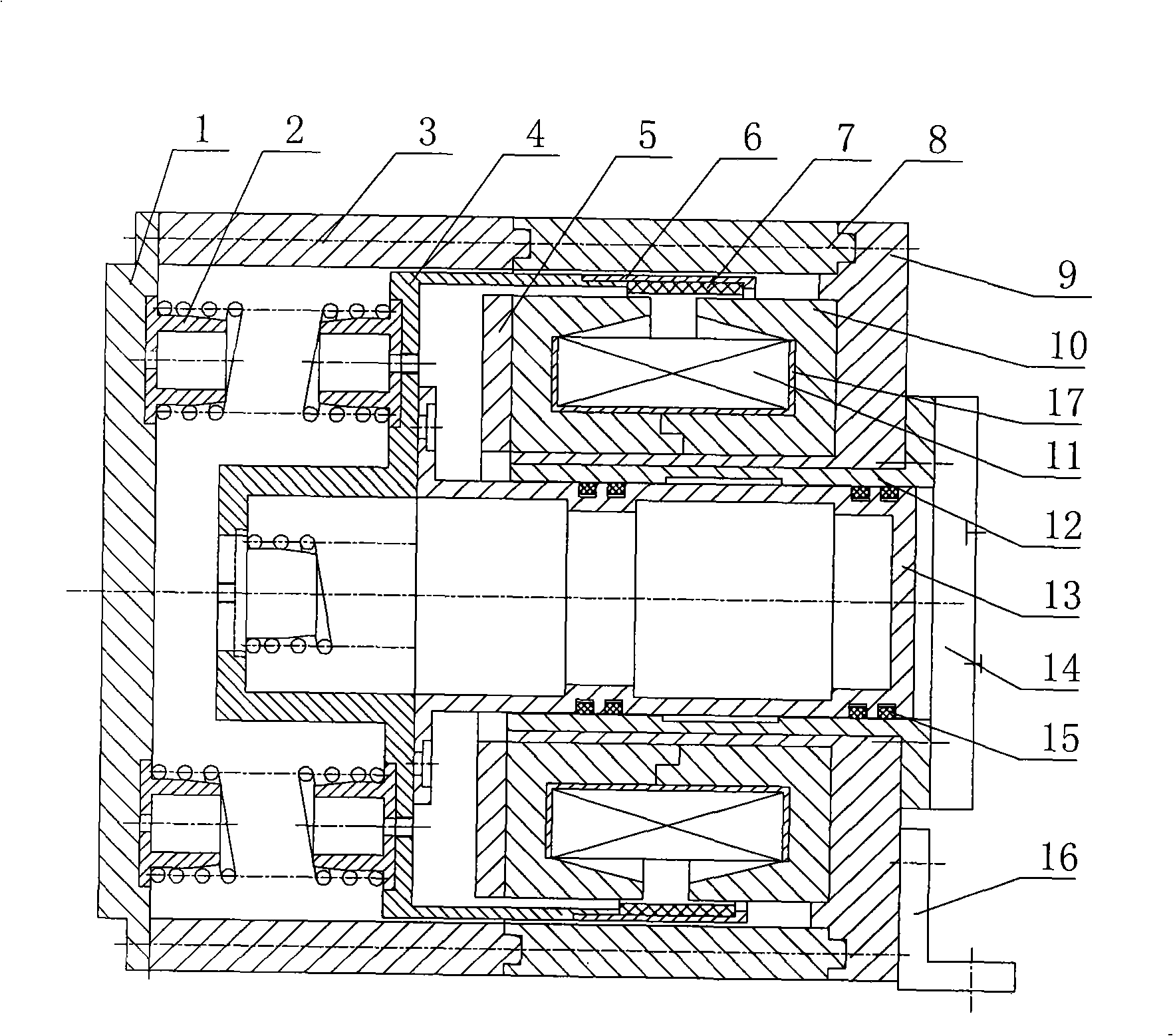
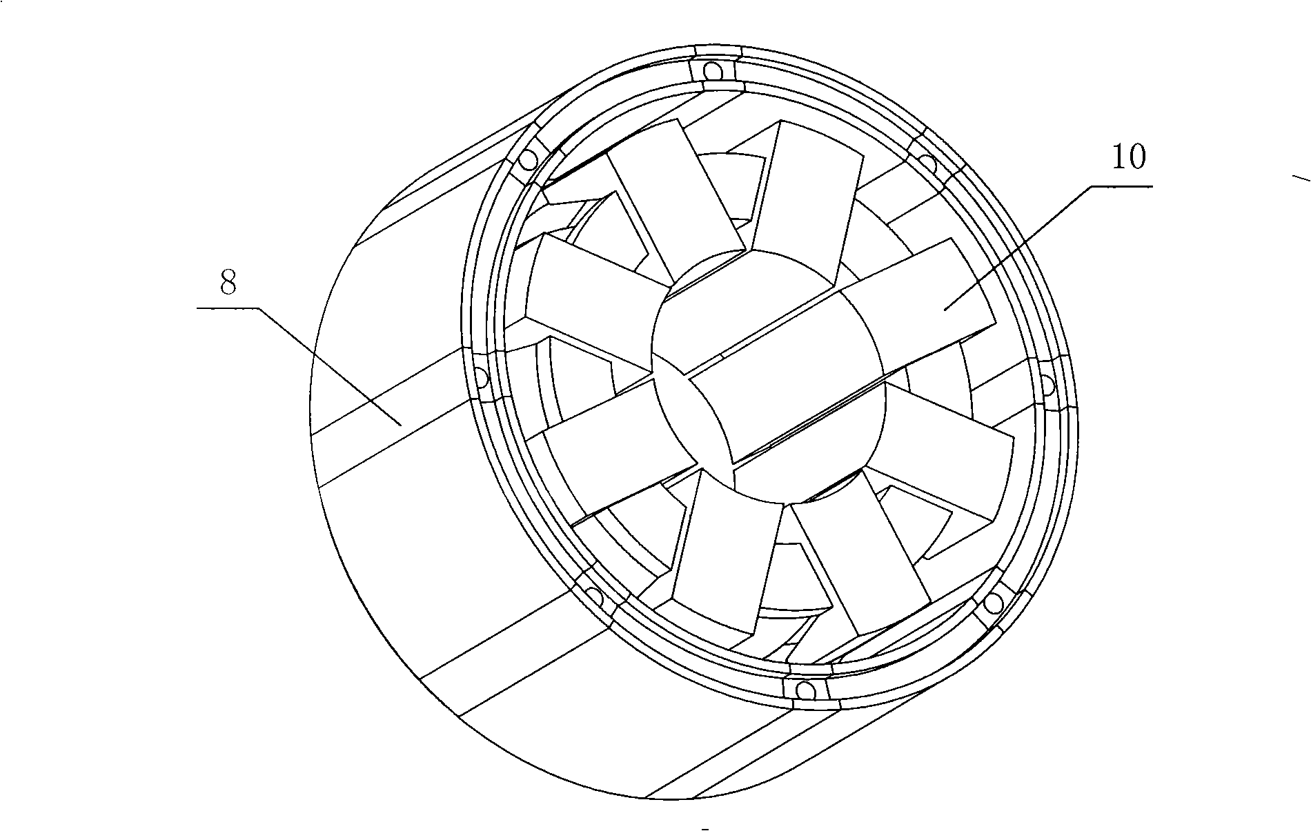
[0024] See Figure 2 ~ Figure 4 This embodiment includes the cylinder 12, the piston 13, the suction and exhaust valve assembly 14, the mover bracket 4, the outer end cover 1, the resonance spring 2, and the inner yoke part, the outer yoke part and the magnet part, the piston 13, the mover The bracket 4 and the magnet component form a motor mover. The piston 13 is located in the cylinder 12 and is fixed to the mover bracket 4. The suction and exhaust valve assembly 14 is fixed at the tail of the cylinder 12, and a piston ring 15 is provided between the piston 13 and the cylinder 12 , A pair of resonance springs 2 are fixed in the cavity between the outer end cover 1 and the mover bracket 4, and the motor mover can move linearly in the cylinder.

[0025] Among them, the inner yoke component includes a coil 11 and several inner silicon steel sheets 10 with cavities. The inner silicon steel sheets 10 are uniformly distributed on the outer wall of the cylinder 12 in a ring shape, and t...

Embodiment 2

[0033] Referring to Fig. 5, this embodiment is composed of two identical linear air compressors on the left and right sides, and the two compressors are fixed together to form a counter-moving structure. The structure of each compressor is the same as in the first embodiment.

[0034] When the air compressor of the present invention is operating, the piston 13 reciprocates in the cylinder 12, which will generate reciprocating inertial force. This inertial force and the moment of inertia caused by these forces belong to free force and free moment. They will cause the foundation and compressor to vibrate, resulting in fragile mechanical parts and increased power loss. Since the movement of the piston 13 is not converted from a rotational movement, but the motor mover directly drives the piston 13 to make a linear reciprocating movement, there is no rotational inertia force.

[0035] This embodiment is a counter-acting structure. When the coil 11 receives current, the left piston 13 ...


PUM


Abstract

The invention discloses an air compressor, in particular to a linear air compressor without a crank and connecting rod structure. The air compressor comprises a motor mover and an air cylinder; wherein the motor mover capable of moving linearly is positioned in the air cylinder. The air compressor is structurally characterized in that an internal yoke component and an external yoke component are further included, wherein, the internal yoke component comprises a coil and a plurality of internal silicon steel sheets with internal hollow cavities, the internal silicon steel sheets are distributed and fixed on the external wall of the air cylinder, and the coil is positioned in the hollow cavities of the internal silicon steel sheets; the external yoke component comprises external silicon steel sheets, and clearance is formed between the external silicon steel sheets and the internal silicon steel sheets; a magnet part of the motor mover is positioned in the clearance. The linear air compressor with the motor mover directly connected with the piston and without the crank and the connecting rod structure has the advantages of small friction, high efficiency, low vibration and compact structure.

Description

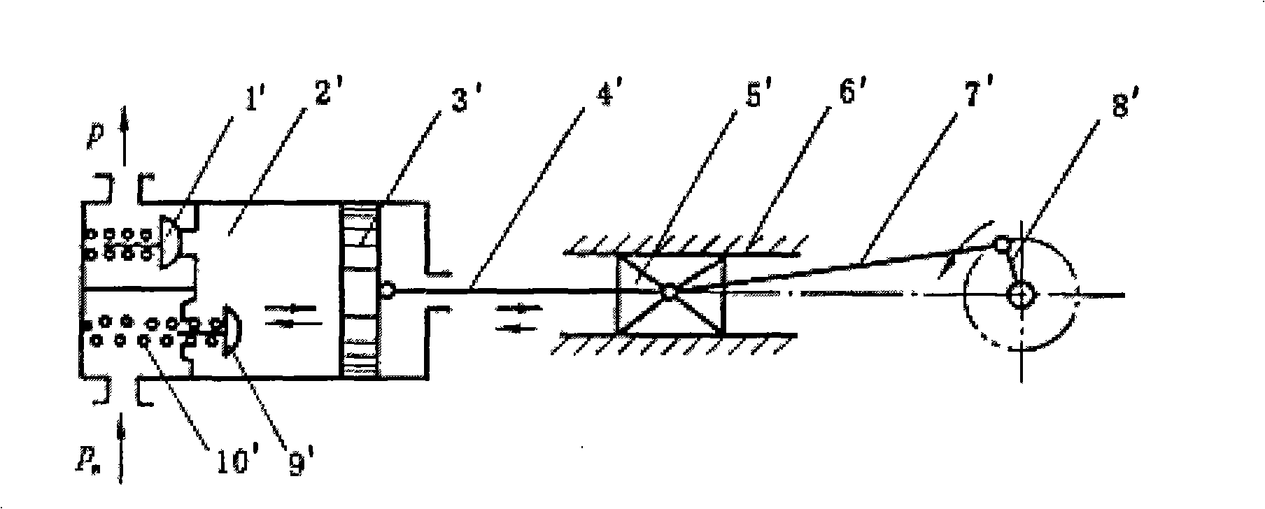
Technical field [0001] The invention relates to an air compressor, in particular to a linear air compressor without a crank connecting rod structure. Background technique [0002] Air compressors are often used to provide compressed air for operating tools, such as nailing tools, socket wrench drive tools, raw material forming tools, sanding tools, painting tools, inflatable chucks and similar pneumatic tools. [0003] Most traditional air compressors use a rotary motor to drive the piston to reciprocate through a conversion mechanism to achieve the purpose of compressing gas. The rotary motor provides rotary motion. For example, the linear motion of the piston must have a conversion mechanism. The usual conversion mechanism is Crank Mechanism. Common structures such as figure 1 As shown, the rotating motor drives the crank 8'to rotate, the crank 8'drives the crosshead 5'to slide in the slide 6'through the connecting rod 7', and the crosshead 5'then drives the piston 3'in the cy...

Claims


Application Information

Patent Timeline
Patent Type & Authority Applications(China)
IPC IPC(8): F04B35/04H02K33/18
Inventor 郑水英李志海潘晓弘刘晓辉刘淑莲钟美鹏
Owner ZHEJIANG UNIV
Learn More