
Modular pump unit used in multi-stage pump

A modular, pump unit technology, applied to the components, pump components, pumps, etc. of the pumping device for elastic fluids, which can solve the problem of limiting the working conditions of the multi-stage pump, the structure of stress concentration, and affecting the service life, etc. problems, to achieve the effect of increasing operating conditions, prolonging shaft life, and improving shaft life

Active Publication Date: 2011-09-14
CHINA UNIV OF PETROLEUM (EAST CHINA)
View PDF5 Cites 10 Cited by
  • Summary
  • Abstract
  • Description
  • Claims
  • Application Information

AI Technical Summary

Problems solved by technology

[0003] At present, multi-stage centrifugal pumps usually use a main shaft to drive the impellers at all levels to rotate, and the axial force self-balancing is realized through the balance mechanism and the symmetrical arrangement of the impellers. The main shaft is usually a multi-step shaft section, which makes the main shaft structure too complicated, resulting in structural comparison of stress concentration. Many, resulting in local stress concentration of the spindle, affecting the service life
[0004] In addition, due to the fixed length of the main shaft of the current multi-stage centrifugal pump, the number of stages of the multi-stage pump is fixed, which limits the working conditions of the multi-stage pump to a certain extent.

Method used


Image

  • Modular pump unit used in multi-stage pump
  • Modular pump unit used in multi-stage pump
  • Modular pump unit used in multi-stage pump

Examples


Embodiment Construction

[0013] The present invention will be further described below in conjunction with the accompanying drawings and embodiments.

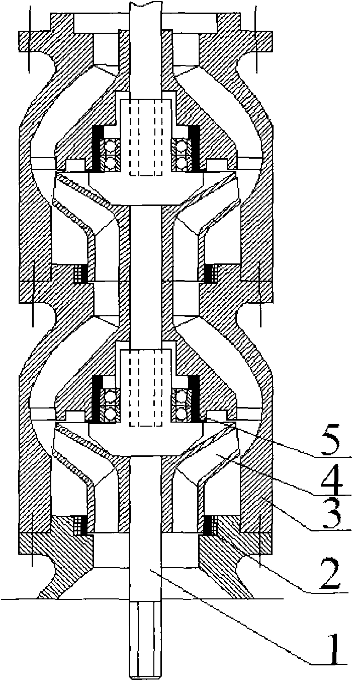
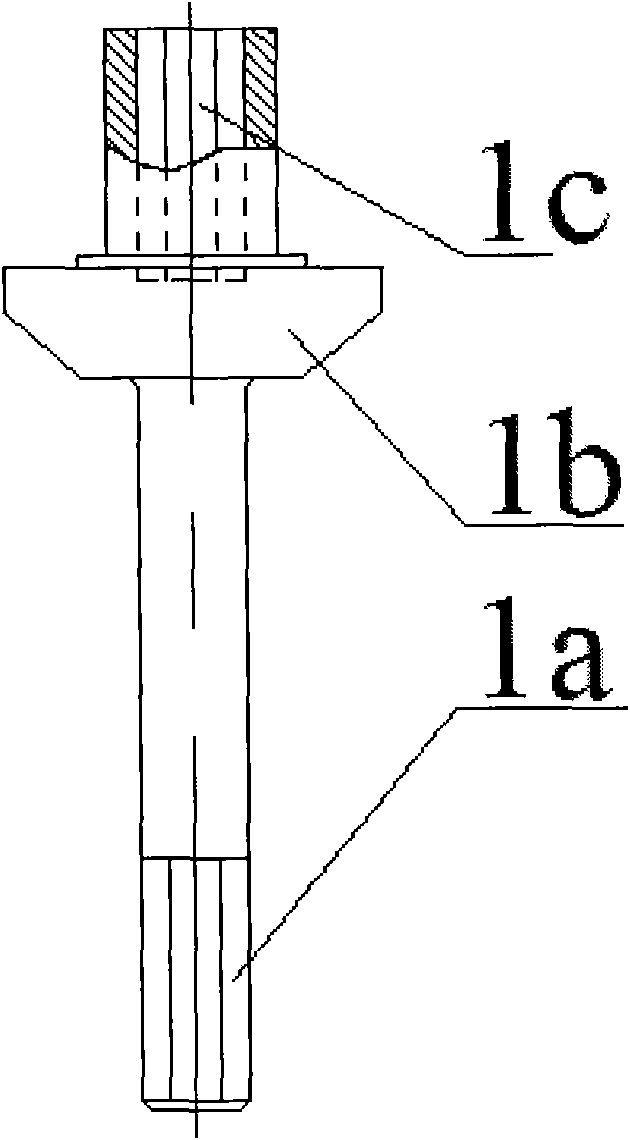
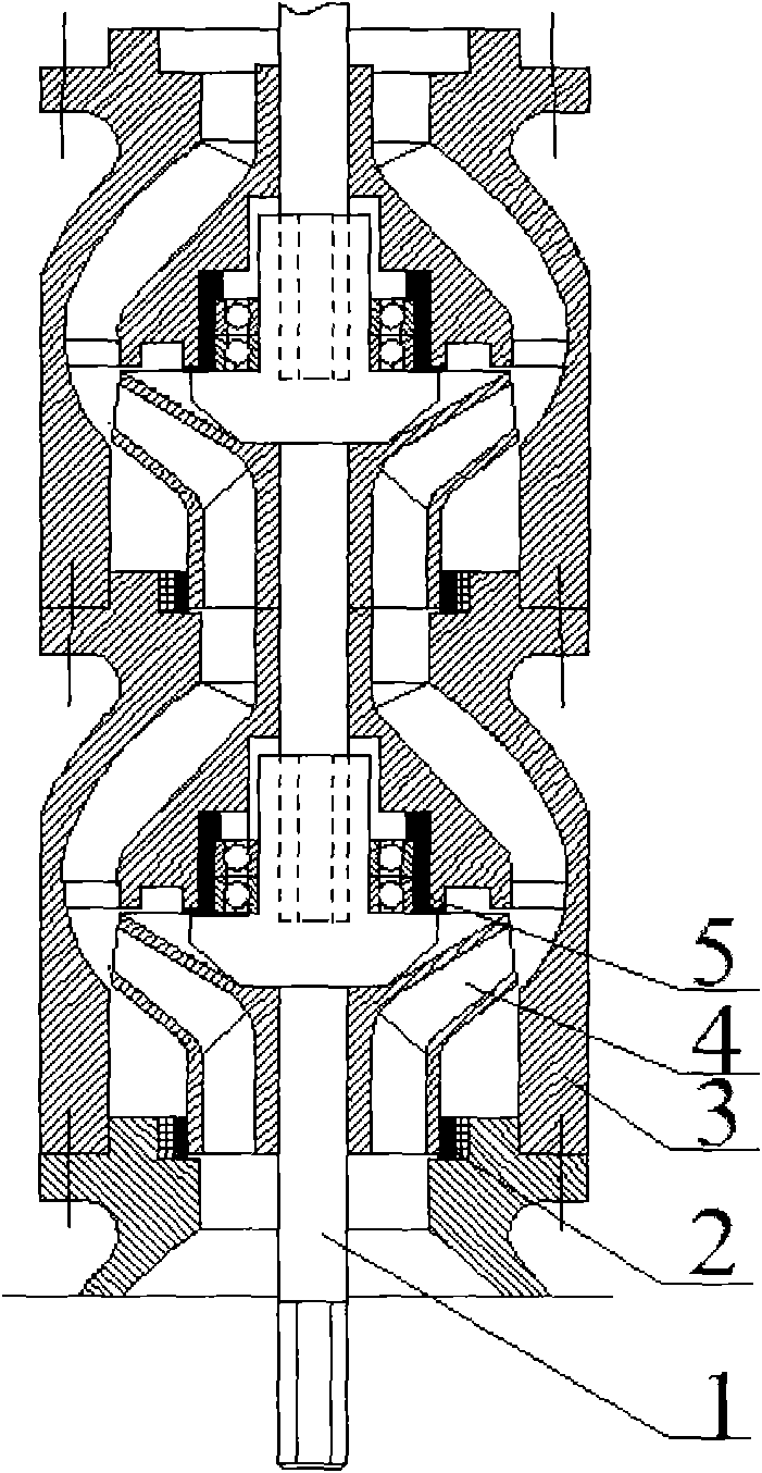
[0014] refer to figure 1 It is a structural schematic diagram of an embodiment of the present invention for a multi-stage pump. The single-stage modular pump unit is composed of a modular pump shaft unit 1, a single-stage bearing system 5, an impeller 4, a mouth ring 2 and a pump casing surrounded by the impeller. 3 components; when assembling, first assemble a single-stage pump unit, the single-stage pump shaft unit is connected to the lower-stage pump shaft through a hexagonal shaft head or thread or spline, and the pump casing is connected by bolts; the same multi-stage pump can be used according to the use The working conditions require that the number of pump stages can be increased or decreased quickly and easily to achieve the required pump head.

[0015] The shaft drives the impeller to rotate through the key, and the fluid medium is driven by ...


PUM


Abstract

The invention relates to a modular pump unit used in a multi-stage pump. A multi-stage main shaft in the multi-stage pump is used for driving an impeller to rotate and is provided with a plurality of sets of bearing systems; and single-stage modular shaft units are arranged in series, the stage number of the same pump is not constant and can be quickly and easily increased or reduced according to the requirement of working condition. By the modular pump unit, the design complexity of the main shaft of the multi-stage pump is avoided, the intensity and the hardness of the main shaft are enhanced, the axial force and the radial force applied to the shaft are reduced, so that the service life of the shaft is prolonged, the accident of shaft broken of the multi-stage pump is reduced to a great extent, the modular processing production is realized, and the application range of the multi-stage pump is expanded. Moreover, the modular pump unit has higher promotion value and practical meaning.

Description

technical field [0001] The invention relates to the field of fluid conveying machinery, in particular to a modular pump unit used in multistage pumps. Background technique [0002] The multi-stage centrifugal pump is equipped with more than two impellers connected in series, which can achieve a higher lift compared with a single-stage centrifugal pump; compared with a piston pump, a diaphragm pump, etc., it can pump a larger flow. Multistage centrifugal pumps have high efficiency and can meet the needs of high head and high flow conditions, and have been widely used in petrochemical, electric power, construction, fire protection and other industries. [0003] At present, multi-stage centrifugal pumps usually use a main shaft to drive the impellers at all levels to rotate, and the axial force self-balancing is realized through the balance mechanism and the symmetrical arrangement of the impellers. The main shaft is usually a multi-step shaft section, which makes the main shaf...

Claims


Application Information

Patent Timeline
Patent Type & Authority Applications(China)
IPC IPC(8): F04D1/06F04D29/22F04D29/043
Inventor 陈国明尹树孟周昌静许亮斌
Owner CHINA UNIV OF PETROLEUM (EAST CHINA)
Learn More