Method of Manufacturing a Fibre-Reinforced Part for a Wind Power Plant

Active Publication Date: 2008-12-11
LM GLASSFIBER
View PDF4 Cites 30 Cited by
  • Summary
  • Abstract
  • Description
  • Claims
  • Application Information

AI Technical Summary

Benefits of technology

[0008]This is accomplished by a method of manufacturing fibre-reinforced parts for a wind power plant, such as eg a blade, wherein the method comprises laying out different layers comprising layers of fibre-reinforced material in the interior surface of an open mould, and wherein resin is finally applied for mutual adhesion between the laid layers. Outermost on the interior surface of the open mould, several layers of film are arranged. When a film is used for the outermost layer, a moulding process results that will provide a major improvement of the working conditions. It is a further advantage that, compared to the use of gelcoat, a surface is provided which is more resistant to physical impacts in the form of eg cyclical stresses on the element. Moreover a manufacturing process is accomplished which is relatively quick since the laying as such of the film is expedient and considerably faster than the application of gelcoat. For instance, the film can consist of thermoplastics or a thermo-hardening plastics material, and according to one embodiment the film may comprise a fibre-reinforcement. Arrangement of severa

Problems solved by technology

In connection with such moulding process, the use of gelcoat is associated with major drawbacks with regard to the working environment, ia due to it having a large content of styrene, and ia during the hardening process inconvenient vapours are emitted.
However, typically further treatment will always be needed, and the presence of staff in relatively close contact with the gelcoat layer will always be required for the further process.
A further problem of gelcoat is that it is a brittle material and there is a risk of air pockets forming on the final surface.
In connection with blades for wind turbines this may mean that water may collect in the pockets meaning that t

Method used


Image

  • Method of Manufacturing a Fibre-Reinforced Part for a Wind Power Plant
  • Method of Manufacturing a Fibre-Reinforced Part for a Wind Power Plant
  • Method of Manufacturing a Fibre-Reinforced Part for a Wind Power Plant

Examples


Embodiment Construction

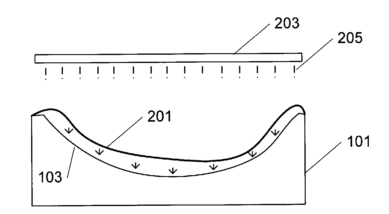
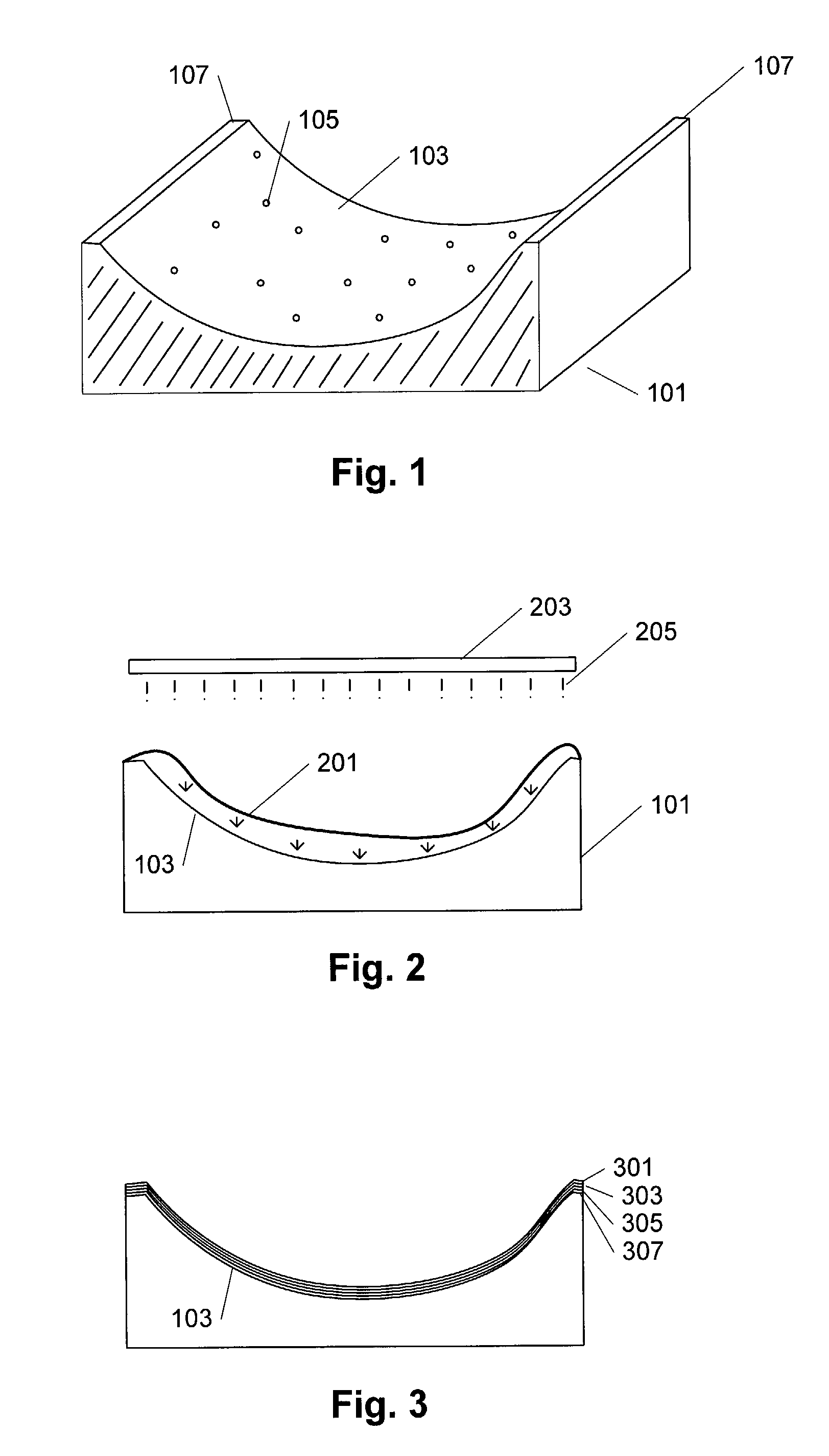
[0027]FIG. 1 shows a sectional view of an open mould 101 that can be used in connection with the manufacture of a fibre-reinforced part, wherein the outermost layer of the part is a film. The interior surface 103 of the mould comprises a number of vacuum holes 105 and an edge 107. The open mould is used in that a layer of film, preferably a thermoplastics film, is arranged on the interior surface 013 of the mould; the film is adapted to the shape of the interior surface of the open mould in that a vacuum is provided between the mould and the film. This takes place by air being sucked out of the vacuum holes, and in that context the film could initially be attached or secured to the edge 107 to enhance the vacuum effect. Then a number of layers of fibre material are arranged, following which resin is finally added to adhere the individual layers of fibre material to each other, and when the resin is cured a fibre-reinforced portion is formed where the film constitutes the outermost l...


PUM

PropertyMeasurementUnit
Shapeaaaaaaaaaa
Thermoplasticityaaaaaaaaaa

Abstract

The invention relates to a method of manufacturing fibre-reinforced parts for a wind power plant such as eg a blade, wherein the method comprises laying out a first, outermost layer of film in the interior surface of an open mould; following which different layers are arranged on top of the first layer, comprising layers of fibre material; and wherein resin is applied for joining the laid-out layers to each other. By use of a film for the outermost layer a moulding process results that provides a major improvement of the working conditions. A further advantage is also that, compared to the use of gelcoat, a surface is accomplished which is more resistant to physical influences in the form of eg cyclical stresses on the element. The invention also relates to a fibre-reinforced part for a wind power plant, eg a blade, wherein the part is structured from a first, outermost layer, and also to a blade for a wind power plant and comprising a fibre-reinforced part according to the invention.

Description

[0001]The invention relates to a method of manufacturing fibre-reinforced parts for a wind power plant, such as eg a blade. The invention also relates to a fibre-reinforced part for a wind power plant such as eg a blade. Finally the invention relates to a blade for a wind power plant comprising a fibre-reinforced part.BACKGROUND[0002]In the context of manufacturing fibre-reinforced parts, eg blades for a wind power plant, a manufacturing process is typically employed in which the blade is moulded in two halves in each their open mould, wherein a coat of gelcoat is initially applied onto the interior surface of the open mould. A number of layers of fibre material are subsequently arranged, following which resin is finally applied to attach the individual layers of fibre material to each other. The resin can be applied to the layers manually by RTM (resin transfer moulding), VARTM (vacuum assisted resin transfer moulding) or other suitable methods. Alternatively the resin can be appli...

Claims


Application Information

Patent Timeline
IPC IPC(8): F03B3/12
CPCB29C70/086B29C70/30B29C2035/0822B29C2037/0042B29C2791/006B29L2031/08B29L2031/085F03D1/065F03D11/0025F05B2230/23F05B2280/4007F05B2280/6003F05C2225/08F05C2253/04Y02E10/721Y02E10/722F03D80/40Y02E10/72Y02P70/50
Inventor LIEBMANN, AXEL
Owner LM GLASSFIBER
Why Eureka
Try Eureka