X-ray recording device with an X-ray detector and an X-ray emitter

a recording device and detector technology, applied in the field of xray recording (imaging) devices with detectors and emitters, can solve the problems of increasing costs, x-ray recording devices, and examining peripheral areas of the patient's body and/or the extremities of the patient, so as to reduce costs, space-saving and as stable

Inactive Publication Date: 2009-10-06
SIEMENS AG
View PDF19 Cites 30 Cited by
  • Summary
  • Abstract
  • Description
  • Claims
  • Application Information

AI Technical Summary

Benefits of technology

[0010]An object of the invention is to provide an X-ray recording (imaging) device of the aforementioned type in which an alteration to the recording range can be undertaken at reduced cost. Moreover, it is an object of the invention to design the X-ray recording device in a manner which is as space-saving and as stable as possible.
[0011]These objects are achieved by an X-ray recording (imaging) device, wherein that the retainer has only one first pivoting arm rotatably mounted on the stand unit, that rotates around a first vertical rotational axis, and only one second pivoting arm rotatably mounted on the first pivoting arm, that rotates around a second vertical rotational axis. Thus the supporting device can be moved within a range of several decimeters without additionally having to move the stand unit. This allows rapid and easy alteration of the position of the X-ray emitter and the X-ray detector, and thus rapid and easy alteration of the recording range. The recording range of the X-ray recording device is precisely the region which is penetrated by the X-ray radiation emitted by the X-ray emitter. The recording range is generally adjustable.
[0012]With the X-ray recording device according to the invention, all movements of the supporting device that are known from the prior art can be executed. The retainer, however, in contrast to the prior art, technically of relatively simple and compact configuration. Additionally, with the design of the retainer according to the invention it is possible for the X-ray recording device to be structurally stable without additional support and / or fastening of the X-ray recording device to external fixtures. Thus the safety requirements for the X-ray recording device can also be cost-effectively fulfilled, for example with regard to the stability and nevertheless, for example, a parallel displacement of the supporting device of the X-ray recording device is made possible. As a result, the working conditions of the medical personnel can be cost-effectively improved. Furthermore, the retainer allows spatial representations of an object to be examined to be detected with new projection geometries—namely for tomosynthesis.

Problems solved by technology

Such X-ray recording devices, however, have the drawback that only peripheral areas of the body of the patient and / or the extremities of the patient can be examined.
The disclosed X-ray recording device has, however, the drawback that slight alterations to the configuration of the arrangement of the object to the X-ray recording device can be made only at increased cost.
This known medical device, however, has the drawback that it cannot be used as a compact, optionally mobile X-ray recording device.

Method used


Image

  • X-ray recording device with an X-ray detector and an X-ray emitter
  • X-ray recording device with an X-ray detector and an X-ray emitter
  • X-ray recording device with an X-ray detector and an X-ray emitter

Examples


Embodiment Construction

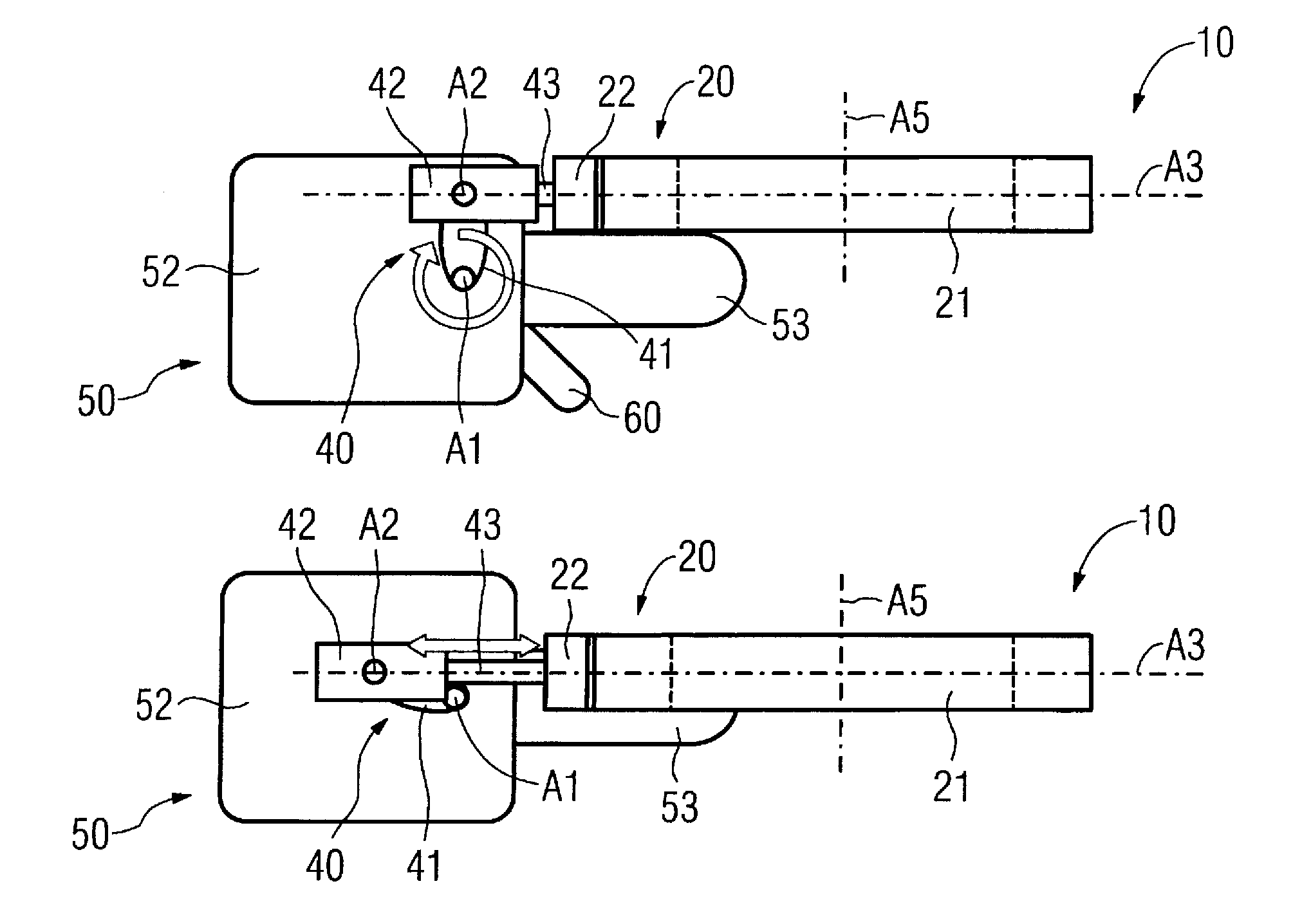
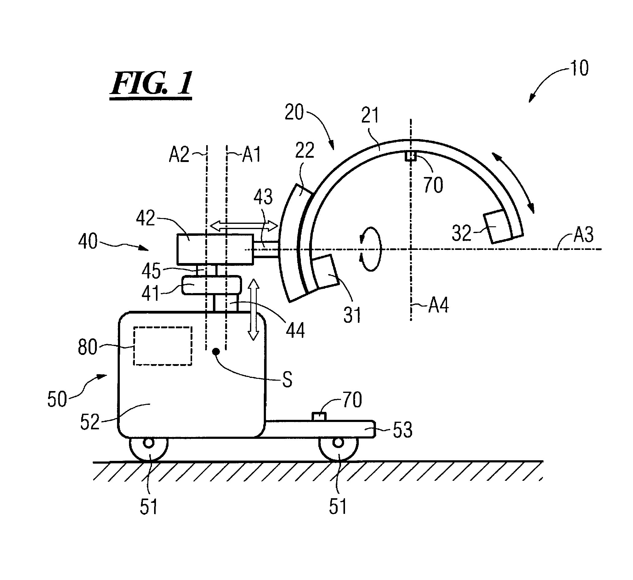
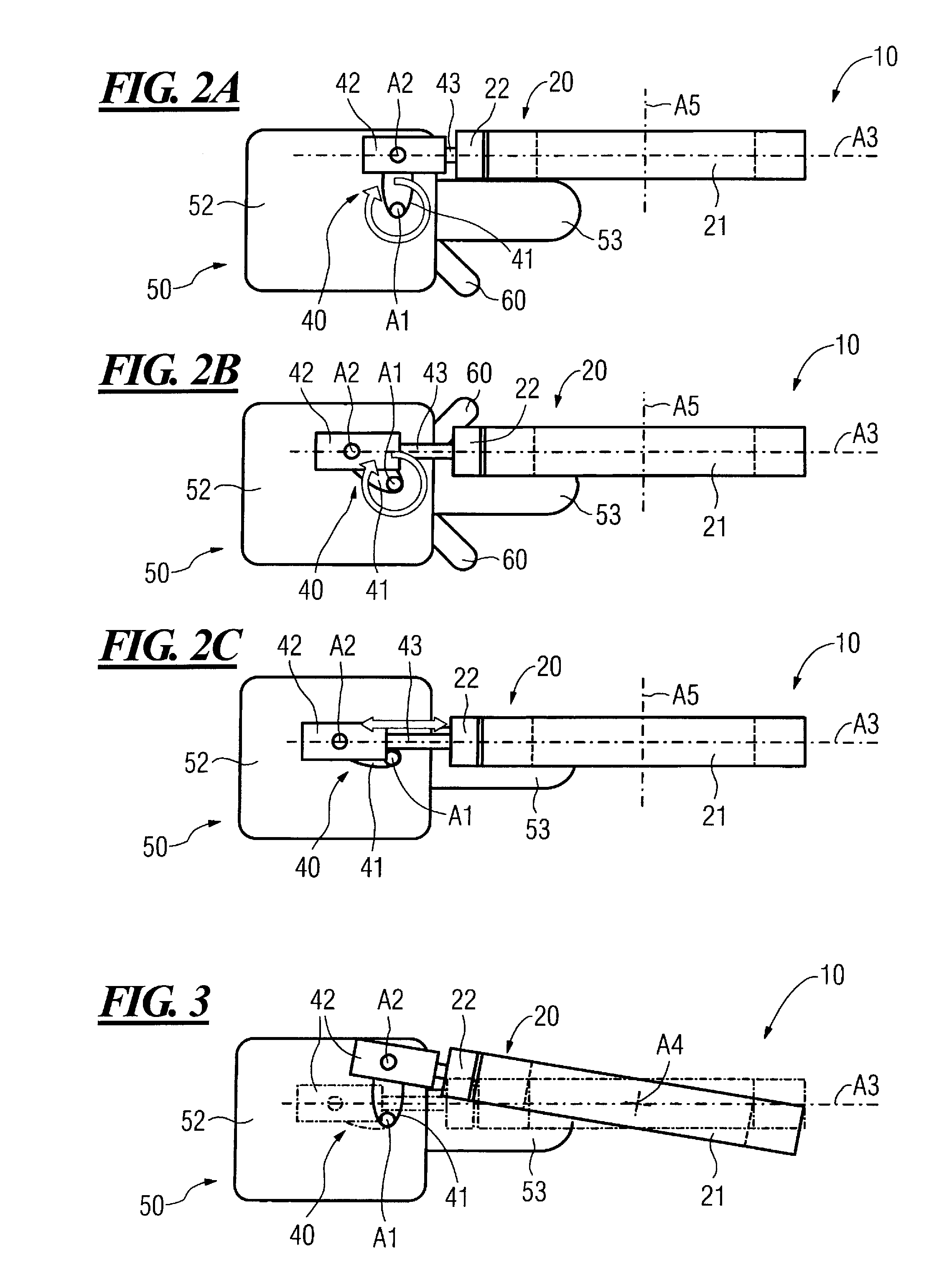
[0032]FIG. 1 shows a mobile C-arm X-ray device 10 with a supporting device 20, which is supported by a retainer 40 on a stand unit 50. The supporting device 20 has a C-arm 21 spanning a C-arm plane and a drive device 22 which is simultaneously configured as guide means and fastening means for the C-arm 21. A rotation of the C-arm 21 is effected by the drive device 22 along its circumference—an orbital rotation—around an orbital axis A5 shown in FIG. 2, as well as a rotation around a horizontal angulation axis A3. Additionally, the retaining means 40 allow a rotation of the supporting device 20 about a vertical axis A4 extending in the C-arm plane. To detect two-dimensional projections of an object to be examined, not shown in FIG. 1, an X-ray emitter 31 and an X-ray detector 32 are provided which are arranged opposite one another, aligned on the C-arm 21. The relative location and position of the X-ray detector 22 and the X-ray emitter 21 always remain unaltered relative to the C-ar...


PUM


Abstract

An X-ray recording device has an X-ray detector and an X-ray emitter aligned with one another on a mobile supporting device, the supporting device being supported by retainer on a stand unit and being displaceable along a horizontal translation axis and / or vertical translation axis. The retainer has only one first pivoting arm rotatably mounted on the stand unit for rotation around a first vertical rotational axis and only one second pivoting arm rotatably mounted on the first pivoting arm for rotation around a second vertical rotational axis. This X-ray recording device allows an alteration to the recording range to be undertaken at reduced cost and with a space-saving and stable configuration.

Description

BACKGROUND OF THE INVENTION[0001]1. Field of the Invention[0002]The present invention relates to an X-ray recording (imaging) device with an X-ray detector and an X-ray emitter, which are aligned with one another on a mobile supporting device, the supporting device being supported by a retainer on a stand unit and being displaceable along a horizontal translation axis and / or a vertical translation axis.[0003]2. Description of the Prior Art[0004]X-ray devices and / or X-ray recording devices are a substantial aid in medical procedures, in spite of advancing developments and further possibilities in the field of radiation-free medical diagnosis. X-ray recording devices, therefore, are encountered in a large number of medical applications. The applications range from X-ray diagnosis, for example the diagnosis of bone fractures, tumors, cysts, calcification, entrapped air or even medical check-ups, including X-ray examinations, for example in angiograms, monitoring of medical intervention...

Claims


Application Information

Patent Timeline
Patent Type & Authority Patents(United States)
IPC IPC(8): H05G1/02
CPCA61B6/4441A61B6/4405
Inventor GRAUMANN, RAINERLUTZ, ERWIN
Owner SIEMENS AG
Why Eureka
Try Eureka