Multipurpose waterproof lighting device with electronic glow stick

a waterproof lighting and electronic glow stick technology, applied in the field of light sources, can solve problems such as rust electronics controlling the devi

Inactive Publication Date: 2012-02-14
DORCY INT
View PDF51 Cites 9 Cited by
  • Summary
  • Abstract
  • Description
  • Claims
  • Application Information

AI Technical Summary

Problems solved by technology

A problem may occur, however, when such electronic devices are used in a water-intensive environment.
That is, water may enter the battery compartment and cause short-circuits, or alternately rust electronics controlling the device.

Method used


Image

  • Multipurpose waterproof lighting device with electronic glow stick
  • Multipurpose waterproof lighting device with electronic glow stick
  • Multipurpose waterproof lighting device with electronic glow stick

Examples


Embodiment Construction

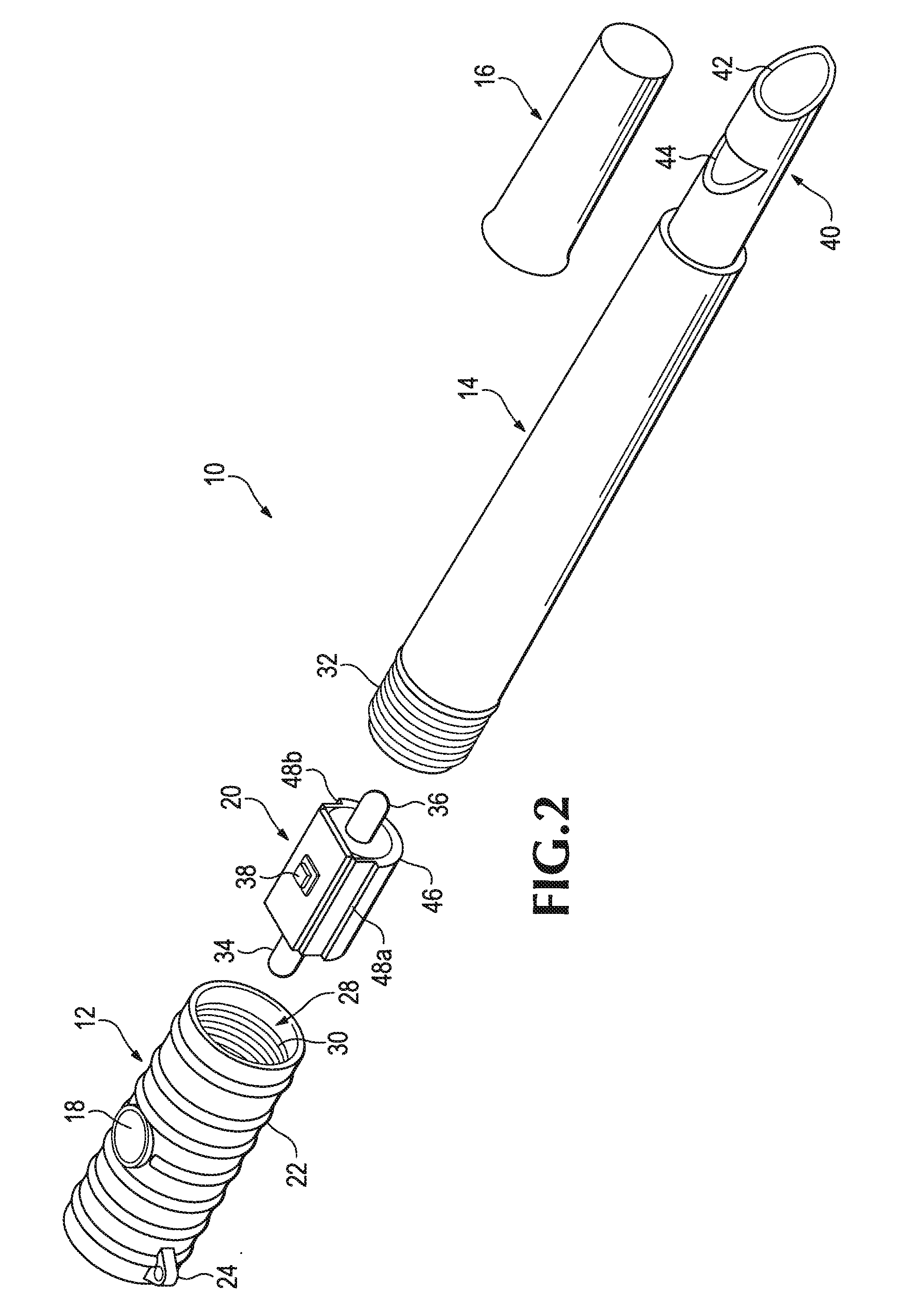
[0020]FIG. 1 illustrates a multipurpose lighting device 10 according to one embodiment of the invention. Device 10 is comprised of a device body having a flashlight housing 12, a glow stick housing 14, and an end cap 16 adjacent one end of the glow stick housing 14.

[0021]A button 18 is defined on a surface of the flashlight housing 12 and interfaces with a button on a lighting module 20 (FIG. 2) as will be described further below. The flashlight housing includes multiple ribs 22 running about the circumference of the housing 12. A flange 24 is fixed at an end of the flashlight housing 12 and couples with a detachable wrist strap 26.

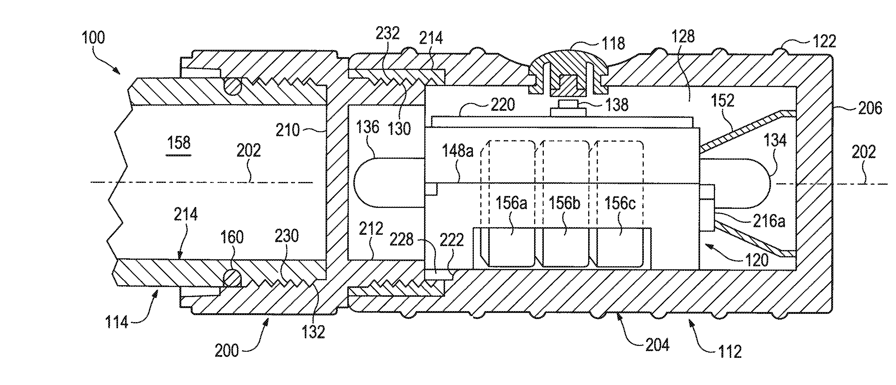
[0022]As illustrated in FIG. 2, the flashlight housing 12 defines a hollow interior 28 into which the lighting module 20 is installed. Female threads 30 formed on the inside walls of the hollow interior 28 mate with male threads 32 formed on the end of the glow stick housing 14, thereby enclosing the interior 28 and fixing the lighting module 20 within th...


PUM


Abstract

A lighting device comprises an elongated assembly forming a water-tight chamber adjacent a first end of the lighting device, where the first end includes a transparent face along a long axis of the elongated assembly. A lighting module, having a first light source and a second light source positioned on opposite ends of the lighting module, is positioned within the water-tight chamber so that the first light source is adjacent to and is configured to project light out the transparent face in a first direction along the long axis of the elongated assembly. The second light source is configured to illuminate along an elongated portion of the elongated assembly, where the elongated portion extends from the water-tight chamber in a second direction along the long axis of the elongated assembly opposite from the first direction, and out translucent circumferential sides of the elongated portion. A button on the module allows one to selectively alternate between the first and second light sources.

Description

CROSS REFERENCE TO RELATED APPLICATIONS[0001]This application is a continuation-in-part of U.S. patent application Ser. No. 12 / 244,663, filed Oct. 2, 2008, now U.S. Pat. No. 7,845,820, issued Dec. 7, 2010, the disclosure of which is herein incorporated by reference.BACKGROUND OF THE INVENTION[0002]This invention relates generally to lighting sources and more particularly to a light source with flashlight and glow stick function that is structured to be used in a water-intensive environment.[0003]Portable lighting is typically designed with the task in mind. Accordingly, flashlights are designed to focus a beam of light for peering into dark corners or cast light longer distances whereas lanterns are designed to cast light short distances but in all directions. One such general lighting source is the chemical-based glow stick. The glow stick embeds two or more chemicals within a hollow plastic tube that, when combined, fluoresce for a brief period of time. To use the glow stick, the ...

Claims


Application Information

Patent Timeline
Patent Type & Authority Patents(United States)
IPC IPC(8): F21V1/00
CPCF21L4/00F21L4/02F21V23/04F21V33/008F21V33/0076F21Y2101/02F21Y2115/10
Inventor BERTKEN, DENNIS
Owner DORCY INT
Why Eureka
Try Eureka