Prosthesis adapted for placement under external imaging

a prosthesis and imaging technology, applied in the field of medical devices, can solve the problems of pain in the lower legs and feet, difficulty in fluoroscopy, and need for circumferential orientation, and achieve the effect of preventing errors

Active Publication Date: 2012-04-17
COOK MEDICAL TECH LLC
View PDF19 Cites 113 Cited by
  • Summary
  • Abstract
  • Description
  • Claims
  • Application Information

AI Technical Summary

Benefits of technology

This patent describes how to make sure that a heart valve replacement is done correctly no matter which way it's approaching through the body - either by going up or down. It uses special markings on the valve itself and on the delivery tool to indicate which direction they should face. These marks help ensure that the valve gets placed properly in relation to the rest of the heart. Overall, this makes the procedure safer and easier for surgeons.

Problems solved by technology

The technical problem addressed in this patent is the need for a prosthesis that can be placed in a vein to treat chronic venous insufficiency. The placement of the prosthesis is important, and previous markers have not been designed to provide useful guidance for the orientation of the prosthesis. The patent seeks to address this problem by providing a prosthesis that has a preferred circumferential orientation within the vessel, which can be readily ascertained under fluoroscopy or other imaging systems. This will allow the clinician to ensure that the prosthesis is correctly rotated within the vessel prior to deployment.

Method used


Image

  • Prosthesis adapted for placement under external imaging
  • Prosthesis adapted for placement under external imaging
  • Prosthesis adapted for placement under external imaging

Examples


Embodiment Construction

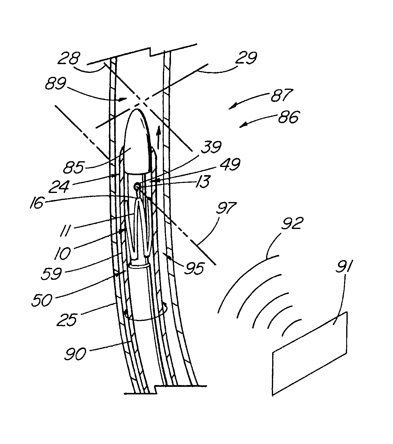
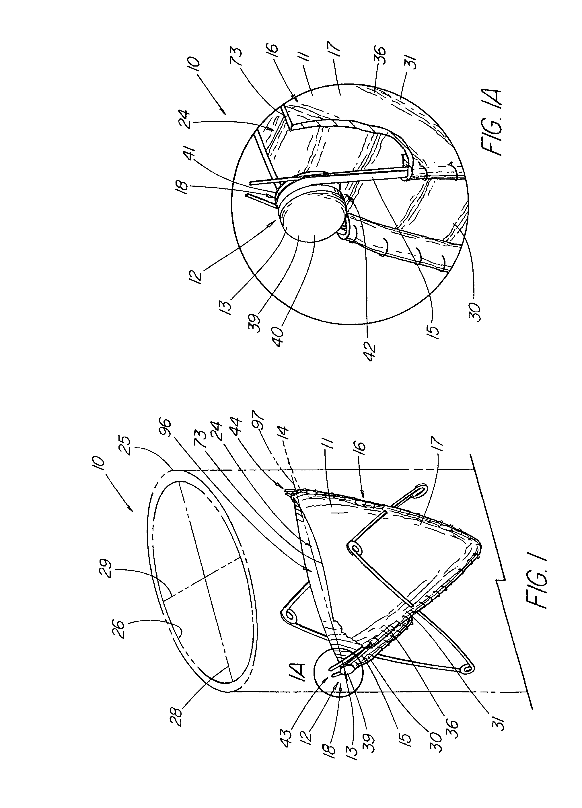
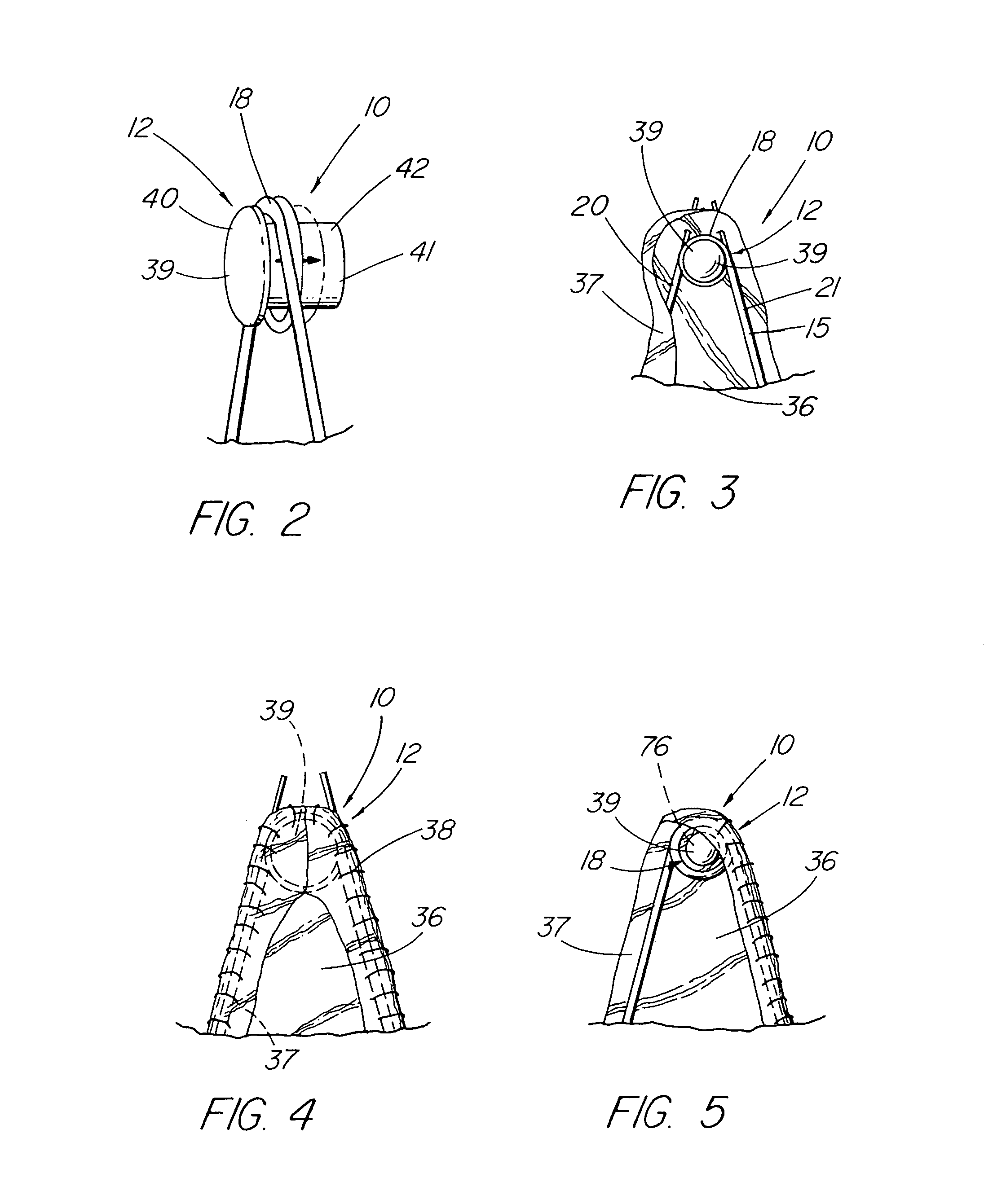
[0039]As embodied in FIGS. 1-23, the present invention is exemplified by an intraluminal prosthesis, typically of a generally tubular or cylindrical shape (cylindrical being defined to include flared or variable-diameter configurations), such as a expandable or self-expanding artificial valve 10, stent, stent graft, occluder, shunt, filter, or the like, that further comprises elements or structure that allows a clinician, using a selected means of external guidance, such as fluoroscopy, X-ray, ultrasound, M.R.I., etc., to readily identify the plane in which the prosthesis, or a particular portion thereof, lies prior to deployment within the patient and / or immediately thereafter. For example, to identify a structural feature 24,82, etc., disposed about a first axis 97 transecting the passageway 96 of the prosthesis, the imageable structure the imageable structure 12 or element is configured or positioned about the axis 97 to allow the clinician to adjust the position of the prosthesi...


PUM


Abstract

A expandable prosthesis having an imageable structure comprising one or more elements visually distinguishable by an external (e.g., radiographic or ultrasonic) imaging system, the structure being located about a first axis that corresponds to a structural feature of the prosthesis that is configured to perform a specific function particular to that axis. The imageable structure is configured to assist in the rotational orientation of the prosthesis during placement within the implantation site. In one embodiment, the prosthesis comprises a venous valve that includes imageable elements or structure, such as a pair of radiopaque markers, that defines the orifice of the valve structure such that the orifice can be oriented with a particular anatomical feature under imaging, such as to align the orifice with the long axis of the vessel. In another embodiment, the imageable structure is configured to permit an aperture located about a stent graft to be oriented with a anatomical feature of the vessel, such as a branch vessel opening. The invention includes a method for using imageable structure to confirm that the orientation of the prosthesis within a delivery apparatus is consistent the desired delivery approach to be used.

Description


Claims


Application Information

Patent Timeline
Owner COOK MEDICAL TECH LLC
Why Eureka
Try Eureka