Image processing apparatus and image processing method

a technology of image processing apparatus and image processing method, which is applied in the direction of picture signal generators, solid-state device signal generators, television systems, etc., can solve the problems of difficult to obtain the precise aberration function necessary to obtain a proper, and the difficulty of reducing chromatic aberration only by optics, so as to reduce unnatural effects and reduce color blur

Inactive Publication Date: 2012-02-14
CANON KK
View PDF5 Cites 3 Cited by
  • Summary
  • Abstract
  • Description
  • Claims
  • Application Information

AI Technical Summary

Benefits of technology

[0014]The present invention is directed to an image processing apparatus and an image processing method which provide image processing that can effectively reduce a color blur that would otherwise appear around a bright part in an image due to a chromatic aberration of an imaging optical system, and that can reproduce original colors. The present invention is also directed to an image processing apparatus and an image processing method which can reduce unnaturalness generated by discontinuous color blur reduction processes between frame images in the motion pictures.
[0018]An image processing method according to still another aspect of the present invention configured to perform a process to reduce a color blur in a color motion picture image utilizing a first frame image and a second frame image that has been obtained after the first frame image includes the steps of storing a first pixel value used for the process to the first frame image, calculating a color blur estimation amount in the second frame image through a spatial operation to the second frame image, calculating an estimation pixel value obtained through the process by using the color blur estimation value to the second frame image, and calculating a second pixel value output as a result of the process to the second frame image so that a difference between the first pixel value and the color blur estimation amount can fall within a predetermined range.

Problems solved by technology

However, as a small size of a digital camera progresses, high resolution image sensors (or image pickup devices) and smaller optical systems are increasingly demanded, and it is difficult to sufficiently reduce the chromatic aberration only by the optics.
The process disclosed in JP 2003-018407 utilizes a deconvolution and its approximate contour emphasis process, but has a problem of a difficulty in obtaining a precise aberration function necessary to obtain a proper result.
It is difficult to precisely recognize an aberration function corresponding to each of huge imaging conditions that include a zoom position, a stop value, a focus position, a size of each lens, and an assembly state.
In addition, the deconvolution can be used only in the linear reaction area of an image sensor, and cannot reduce a color blur around the saturation pixel.
When each of these prior art chromatic aberration reduction processes is applied to a motion picture image obtained by taking a moving high brightness subject, discontinuous processes of a time series of an application and a non-application of the chromatic aberration reduction process generate unnatural motion picture images, bringing a sense of discomfort to a viewer.
The color blur reduction process disclosed in JP 2006-135744 utilizes the previous motion picture image frame and reduces a calculation load, but does not have an effect of mitigating a sense of discomfort caused by the discontinuous color blur reduction processes.

Method used


Image

  • Image processing apparatus and image processing method
  • Image processing apparatus and image processing method
  • Image processing apparatus and image processing method

Examples


first embodiment

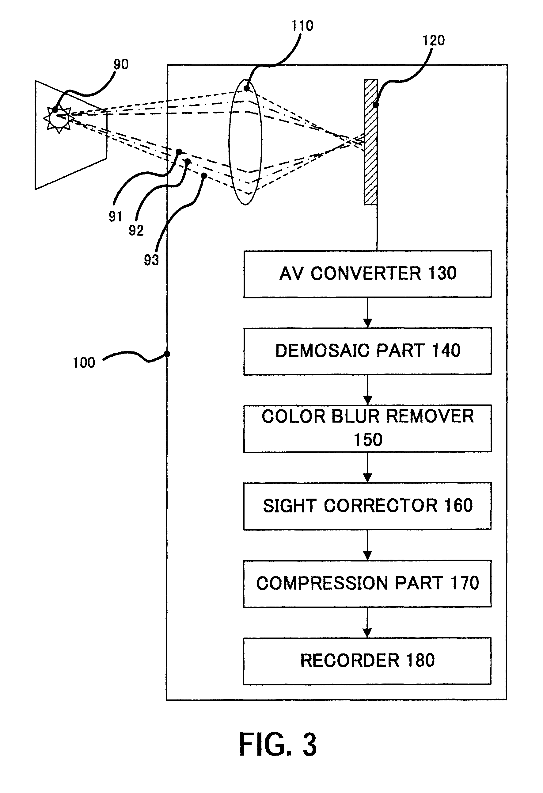
[0036]FIG. 3 shows a color image pickup apparatus 100 that utilizes an image processing method or is mounted with an image processing apparatus according to a first embodiment of the present invention.

[0037]The color image pickup apparatus 100 includes an imaging optical system 110, an image sensor 120, an AD converter 130, a demosaic part 140, a color blur remover 150, a sight corrector 160, a compression part 170, and a recorder 180.

[0038]Although a view field (imaging area or subject) shown in FIG. 3 and an R (red) ray 91, a G (green) ray 92, and a B (blue) ray 93 are not the elements of the color image pickup apparatus 100, they are illustrated for description purposes.

[0039]In FIG. 3, the taken view field 90 is imaged on the image sensor 120 via the imaging optical system 110. In general, an imaging optical system in a color image pickup apparatus is provided with a certain chromatic aberration correction. The longitudinal chromatic aberration of the imaging optical system 110 ...

second embodiment

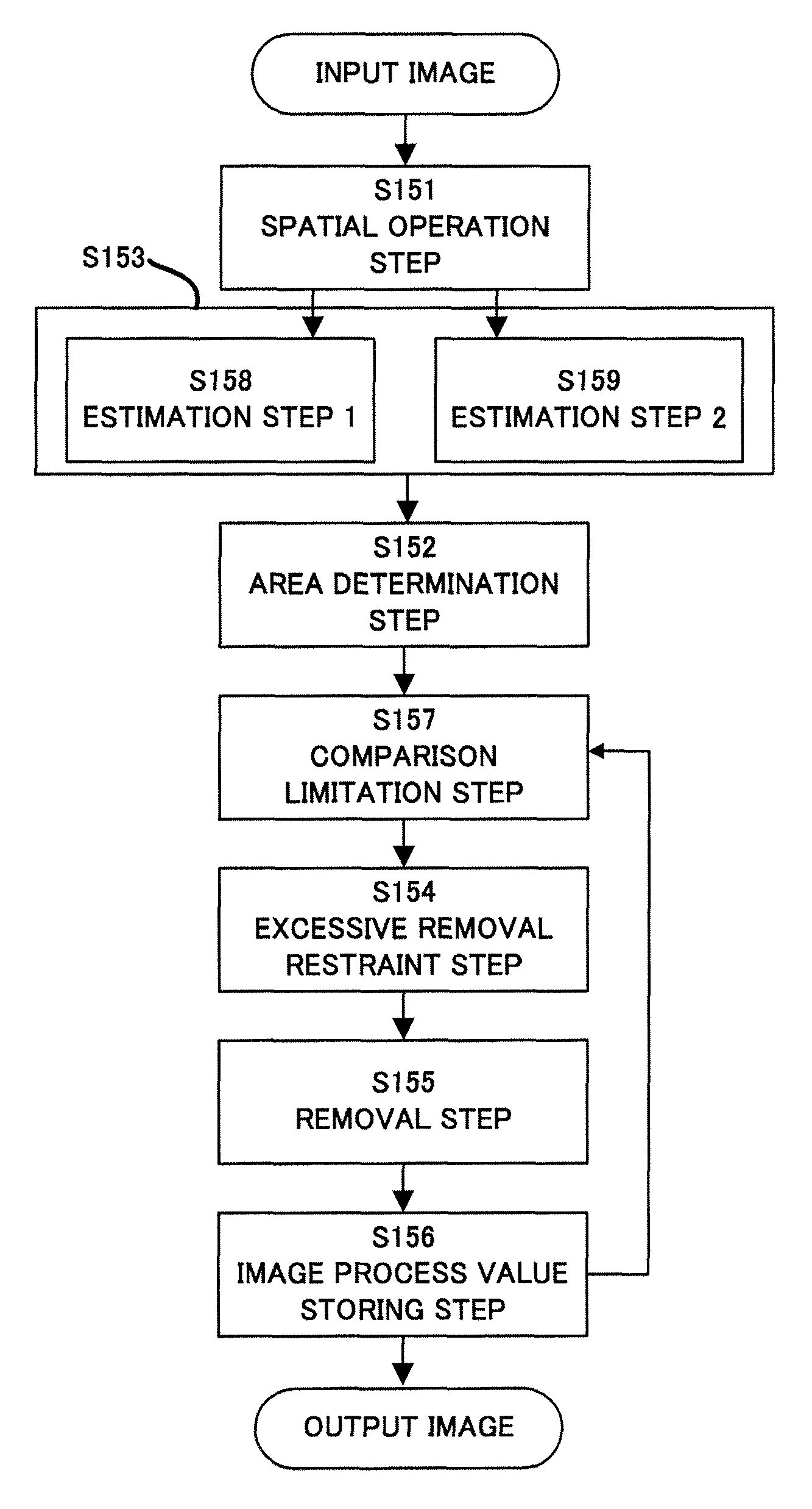
[0097]Next follows a description of a second embodiment according to the present invention. The first embodiment restricts the color blur estimation amount E, whereas this embodiment restricts the B plane intensity after the color blur estimation amount is removed (or the image pixel value of the second frame image after the color blur reduction). Therefore, the process performed by the color blur remover 150 in the color image pickup apparatus shown in FIG. 3 is different from the first embodiment.

[0098]Referring to a flowchart of FIG. 12, a description will be given of a process of the color blur remover 150 of this embodiment. The color blur remover 150 includes a spatial operation step 1151, an estimation step 1153, an area determination step 1152, a removal estimation step 1158, a comparison limitation step 1157, an excessive removal restraint step 1154, a removal step 1155, and an image process value storing step 1156.

[0099]The above steps 1151 to 1158 can be regarded as the e...

third embodiment

[0114]Next follows a description of a third embodiment according to the present invention. This embodiment discusses an example that changes, based on a spatial operation result, the lower and upper limit values used to restrict the color blur estimation amount described in the first embodiment.

[0115]A point 906 shown in FIGS. 9A-9C is closer to the high brightness subject 901, and has a greater color blur estimation amount than the point 905. When the lower and upper limit values used to restrict the color blur estimation amount are made constant in an image, as understood from a comparison between the B plane intensity 1401 before the color blur removal and the B plane intensity 1402 after the removal shown in FIG. 14, a color blur can be sufficiently removed from the point 905 having a smaller color blur than the upper limit value. However, the color blur cannot be sufficiently eliminated from the point 906 having a color blur that exceeds the upper limit value, and may bring a s...


PUM


Abstract

An image processing apparatus configured to perform a process to reduce a color blur in a color motion picture image utilizing a first frame image and a second frame image that has been obtained after the first frame image includes a memory configured to store a first color blur reduction amount used for the process to the first frame image, an estimator configured to calculate a color blur estimation amount in the second frame image through a spatial operation to the second frame image, and a determination part configured to calculate a second color blur reduction amount used for the process to the second frame image so that a difference between the first color blur reduction amount and the color blur estimation amount can fall within a predetermined range.

Description

BACKGROUND OF THE INVENTION[0001]1. Field of the Invention[0002]The present invention relates to a method of operating an image obtained by a color image pickup apparatus, such as a film camera, a digital camera and a video camera, into a proper image, and a program and apparatus used for the method. The present invention relates more particularly to image processing that makes inconspicuous an originally nonexistent blur color distribution around a bright image.[0003]2. Description of the Related Art[0004]A color image pickup system generates originally nonexistent artifacts in blue, in red, and in purple as a blend of blue and red in a blur shape, around a bright part on an image due to a chromatic aberration of an imaging optical system. This blur is referred to as a color blur or a purple fringe.[0005]A combination of plural lenses having different dispersions can optically reduce the chromatic aberration to some extent. However, as a small size of a digital camera progresses, h...

Claims


Application Information

Patent Timeline
Patent Type & Authority Patents(United States)
IPC IPC(8): H04N5/228
CPCH04N9/045H04N25/611H04N23/843H04N25/134
Inventor UCHIYAMA, SHINZOSAWADA, YASUHIRO
Owner CANON KK
Why Eureka
Try Eureka