Image processing system and image processing method

Inactive Publication Date: 2006-08-24
138 EAST LCD ADVANCEMENTS LTD
View PDF27 Cites 59 Cited by
  • Summary
  • Abstract
  • Description
  • Claims
  • Application Information

AI Technical Summary

Benefits of technology

[0008] An advantage of the present invention is to provide an image processing system that can allow a user to accurately recognize a positional relationship between an image to be composed into a hand-written character and the hand-written character, accurately divide an area of a subject recorded by the user, and print a composite image of the image and the subject.
[0009] (1) An image processing system that achieves the above-described advantage comprises an access unit for accessing a user image stored in a recording medium, a reductive color processing unit for forming a background image by reducing a color gamut of said user image, an order sheet print control unit for causing a printer unit to generate an order sheet on which said background image is printed in a free rendering area, a composition unit for separating from an image in said free rendering area read by a scan unit an area of a subject recorded by a user in said free rendering area based on the color gamut of said background image, and a composite print control unit for causing said printer unit to print said composite image.
[0010] When the image processing system has printed a background image formed by reducing a color gamut of a user image in a free rendering area in which a subject such as a handwritten character is to be recorded by a user, the user can record the subject such as a handwritten character in the free rendering area by accurately recognizing a positional relationship between an image to be composed into a

Problems solved by technology

The printing system, however, has a deep menu hierarchy, which makes operations complicated when a selection of image data to be printed and other manipulations on settings for a number of pages to print and/or a layout, for example, are attempted to receive on a menu displayed on a small screen, which is a problem.
On the other hand, the production costs may disadvantag

Method used


Image

  • Image processing system and image processing method
  • Image processing system and image processing method
  • Image processing system and image processing method

Examples


first example

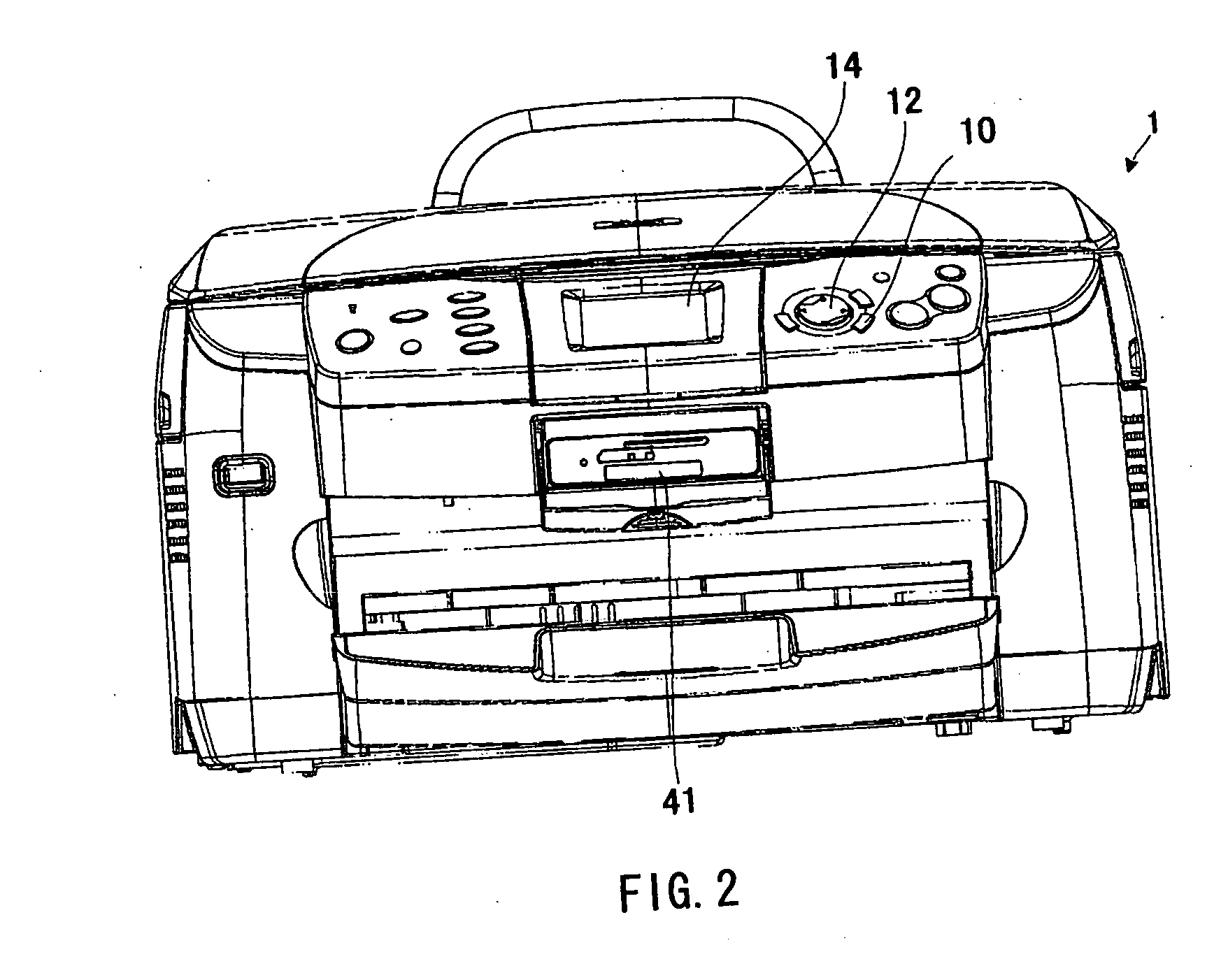
[0027]FIG. 2 is a front view showing an appearance of a multifunction machine 1 according to a first example of an image processing system of the invention. FIG. 3 is a block diagram showing the multifunction machine 1 according to the first example of the invention. The multifunction machine 1 has functions of outputting image data read from an original to a personal computer (PC), not shown, copying an original, printing data output from the PC and printing image data input from a removable memory 3.

[0028] A scan unit 20 of the multifunction machine 1 includes an image sensor 21, an optical system 22, a sensor driver portion 23, a sensor carriage driver portion 24, an Analog Front End (AFE) portion 25, and a digital image processing portion 26.

[0029] The image sensor 21 to be driven by the sensor driver portion 23 is a linear image sensor including a photoreceptive device having three channels for R, G and B and is mounted in a sensor carriage 27, which moves in parallel with an...

second example

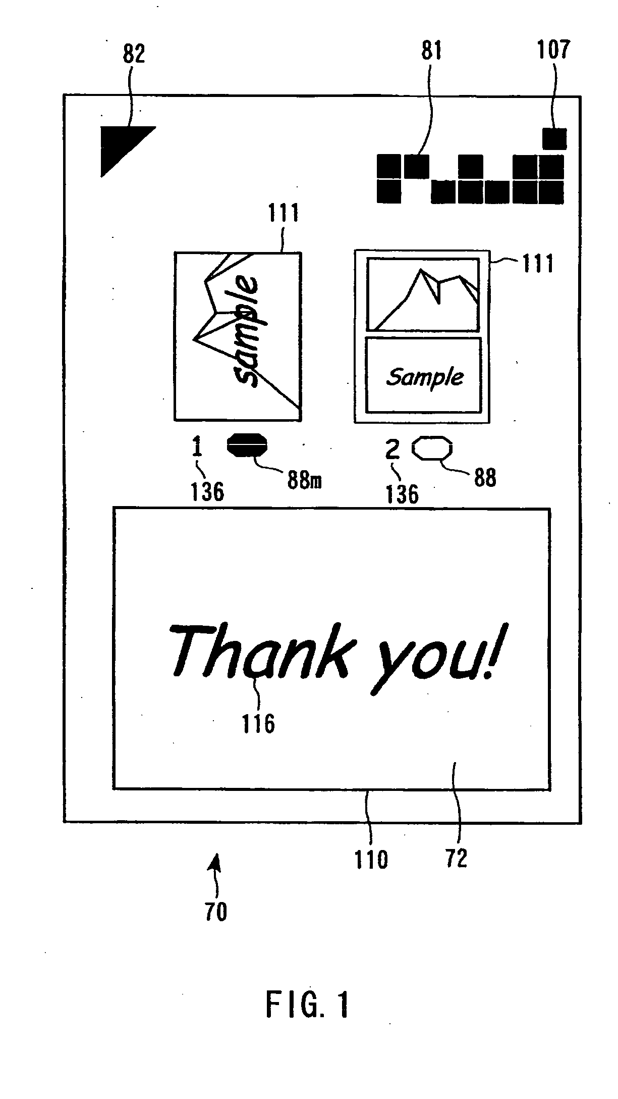
[0065] In a second example of the invention, the verification mark 81 (see FIG. 5) is equivalent to the claimed identifier notation and carries information for specifying a composition template, which will be described more specifically below.

[0066] The pattern of the verification mark 81 depends on a composition template. One or multiple composition template / templates may be selectable by the multifunction machine 1 based on the verification mark 81. In other words, the ability to determine whether hand-written characters, for example, can be recorded on a given order sheet or not based on the verification mark 81 is only required at least. The ability to determine whether a given order sheet is one of multiple kinds of order sheet on which hand-written characters can be recorded or not in accordance with different composition templates is not required from the verification mark 81. The verification mark 81 corresponds to a composition template and also corresponds to the order-sh...

third example

[0075]FIG. 11 is a functional block diagram of the multifunction machine 1 according to a third example of the invention.

[0076] In step S106, the print control module 62 also prints the image selected by the image selection command receiving module 60 on an order sheet based on the order-sheet template 113 shown in FIG. 12. A frame 200 defined by the order-sheet template 113 shown in FIG. 12 is a frame in which an image 202 indicated by the file selected by the image selection command receiving module 60 is to be laid out. The order sheet template 113 accommodates the composite template 120 shown in FIG. 7. That is, an allocation position and size of the image 202 selected by the user and that of the image 122 read from the free rendering area 72 agree with each other on the composite template 120, so that an aspect ratio of the frame 200 and that of the frame 110 agree with each other. The order-sheet template 113 may be defined such that a frame indicating the outer edge of paper...


PUM


Abstract

An image forming system is provided and includes an access unit, a reductive color processing unit, an order sheet print control unit, a composition unit, and a composite print control unit. The access unit accesses a user image stored in a recording medium, the processing unit forms a background image by reducing a color gamut of the user image, and the order sheet print control unit causes a printer unit to create an order sheet on which the background image is printed in a free rendering area. Also, the composition unit separates an area of a subject recorded by a user in the free rendering area from an image of the free rendering area read by a scan unit based on a color gamut of the background image and superimposing the area of the subject on the user image to thereby form a composite image. Finally, the composite print control unit causes the printer unit to print the composite image. A method that the system performs is also provided.

Description

CROSS-REFERENCE TO RELATED APPLICATIONS [0001] This is a continuation-in-part of application Ser. No. 11 / 066,565, filed 2005 Feb. 28. The disclosure of Japanese Patent Application No. 2004-053487 (filed on Feb. 27, 2004), Japanese Patent Application No. 2004-230412 (filed on Aug. 6, 2004), Japanese Patent Application No. 2004-235151 (filed on Aug. 12, 2004), Japanese Patent Application No. 2004-280260 (filed on Sep. 27, 2004), Japanese Patent Application No. 2005-101848 (filed on Mar. 31, 2005), Japanese Patent Application No. 2005-102091 (filed on Mar. 31, 2005), Japanese Patent Application No. 2005-176110 (filed on Jun. 16, 2005), including the specification, drawings and abstract is incorporated herein by reference.BACKGROUND OF THE INVENTION [0002] 1. Field of the Invention [0003] The present invention relates to an image processing system and an image processing method and, more particularly to, a technology for composing a hand-written character and an image stored in a record...

Claims


Application Information

Patent Timeline
IPC IPC(8): G03F3/08
CPCG06T11/60H04N1/3871H04N1/60
Inventor MAKI, YOICHIRONARUSAWA, HIDEYUKIISHIDA, GOROKOJIMA, SHOJIOYANAGI, MAKOTOKOBAYASHI, MASAYA
Owner 138 EAST LCD ADVANCEMENTS LTD
Why Eureka
Try Eureka