Press apparatus

a press and cylinder technology, applied in the field of press cylinders, can solve the problems of affecting the quality of molded glass or resin objects, and breaking of the upper or lower molds,

Inactive Publication Date: 2003-12-25
SUMITOMO HEAVY IND LTD
View PDF6 Cites 22 Cited by
  • Summary
  • Abstract
  • Description
  • Claims
  • Application Information

AI Technical Summary

Benefits of technology

[0014] Thus, at the time of mold closing, the movable mold is smoothly engaged with a stationary mold, since a positional relationship is accurately maintained between the mating surface of the movable mold and that of the stationary mold. Also, breakage of the mold can be avoided.
[0015] Furthermore, since the movable member and the guide member permit accurate positioning of the mating surfaces of the movable and stationary molds, an engagement mechanism which would otherwise be provided on the molds is not required.
[0016] Preferably, the guide surfaces of the movable member or the guide surfaces of the guide member are equipped with corresponding hydrostatic bearings. In this case, since the hydrostatic bearings hold, hydrostatically and in a noncontacting condition, the guide surfaces of the movable member or the guide surfaces of the guide member which face the corresponding hydrostatic bearings, no frictional resistance arises. Thus, the movable member can be moved smoothly in the vertical direction. Therefore, load imposed on the drive unit and the like can be reduced.
[0017] Preferably, the movable member has a hollow portion. In this case, the weight of the movable member can be reduced. Thus, the movable member can be move smoothly in the vertical direction and can be positioned accurately by means of the hydrostatic bearings.
[0018] Preferably, the movable member has a reinforcement member disposed within the hollow portion. In this case, the weight of the movable member can be reduced. Also, since a beam-like member extends across the hollow portion, even when the guide surfaces of the movable member receive external forces, deflection of the guide surfaces can be reduced to the greatest possible extent.

Problems solved by technology

In such a press apparatus, when positional deviation arises between the upper and lower molds, the following problems arise: a molded article fails to assume a predetermined shape, the upper and lower molds fail to engage with each other, or the upper or lower mold is broken.
However, in the conventional press apparatus, the linear bush involves large frictional resistance and great variations in the frictional resistance.
Thus, heavy load is imposed on a drive unit for vertically moving the upper mold; therefore, the drive unit must be of large output, resulting in an increase in the cost of manufacturing the press apparatus and running cost.
Thus, a pressing force which the upper mold applies to a glass or resin material varies; i.e., press-molding cannot be performed at a predetermined pressing force, resulting in impairment in the quality of a molded glass or resin article.
Furthermore, since a gap is unavoidably present between the guide rod and the bush fitted in the guide hole, the guide hole is inclined with respect to the guide rod.
Accordingly, the upper mold is inclined, with a resultant failure to maintain parallelism between the mating surface of the upper mold and that of the lower mold.
This failure leads to uneven surface of a molded article, variations in thickness among molded articles, or impairment in profile transfer to a molded article.
As a result, molded articles fail to exhibit consistent quality.

Method used


Image

  • Press apparatus
  • Press apparatus
  • Press apparatus

Examples


first embodiment

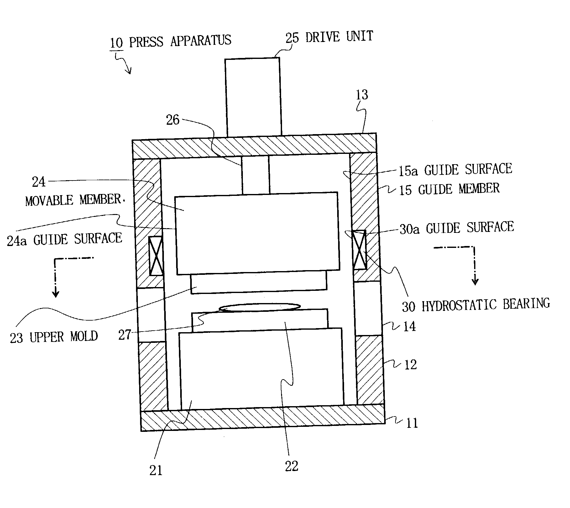
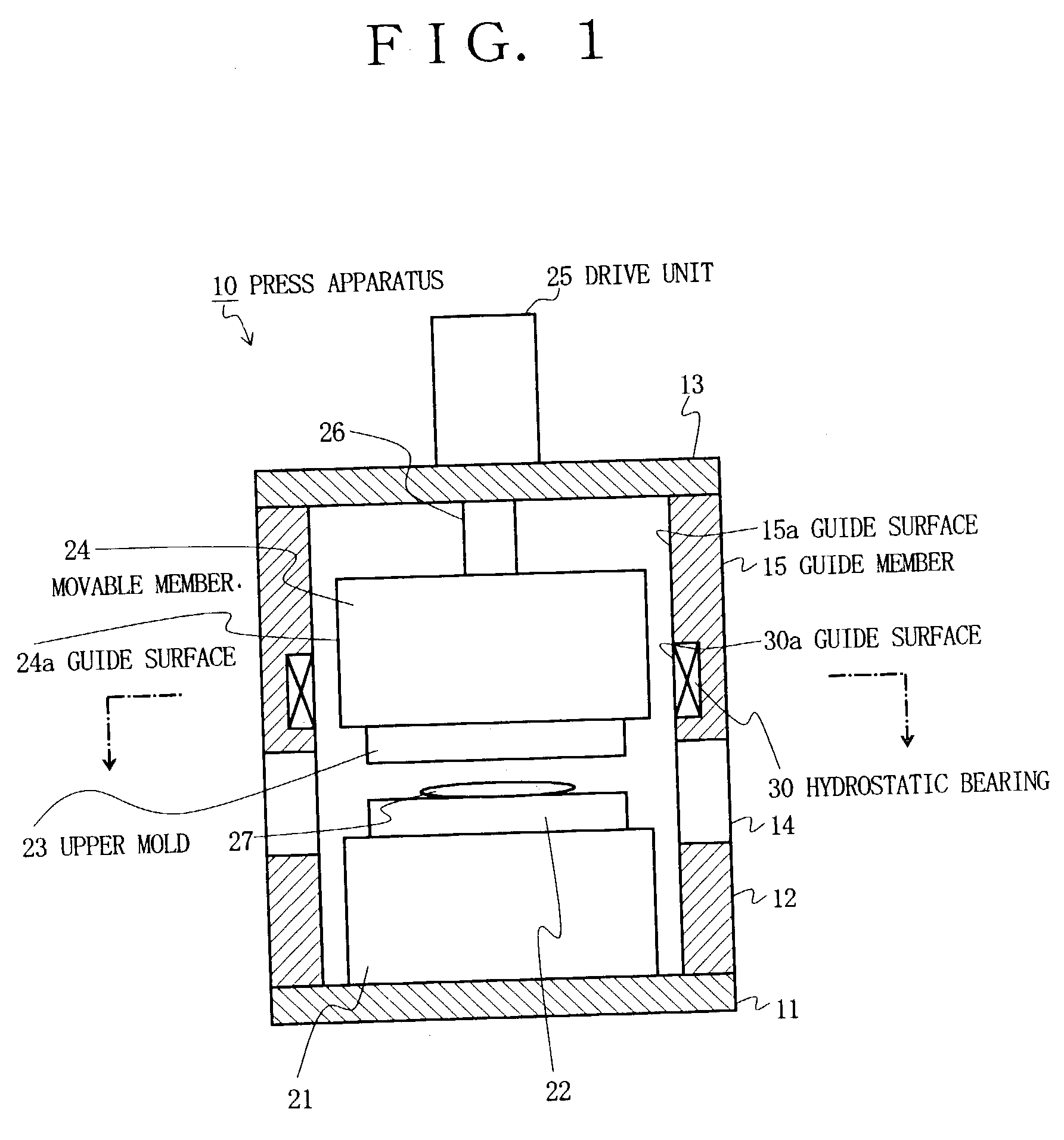
[0046] FIG. 1 is a vertical sectional view showing the configuration of a press apparatus according to the present invention. FIG. 2 is a sectional view taken along line I-I of FIG. 1.

[0047] In FIG. 1, reference numeral 10 denotes a press apparatus; reference numeral 11 denotes a base frame, which serves as a portion of the frame of the press apparatus 10; and reference numeral 12 denotes a guide frame, which serves as a portion of the frame of the press apparatus 10. The guide frame 12 assumes the form of a rectangular prismatic tube in a standing condition, and a lower end portion thereof is attached to the upper surface of the base frame 11.

[0048] A ceiling frame 13, which serves as a portion of the frame of the press apparatus 10, is attached to an upper end portion of the guide frame 12. The base frame 11 and the ceiling frame 13 assume the form of a rectangular plate so as to close opposite end openings of the guide frame 12 in the form of a rectangular prismatic tube.

[0049] A...

second embodiment

[0087] FIG. 5 is a transverse sectional view showing the configuration of a press apparatus according to the present invention.

[0088] In the first embodiment, the hydrostatic bearings 30 are mounted on the corresponding guide surfaces 15a of the guide member 15. The mounting position of the hydrostatic bearings 30 is determined such that the guide surfaces 24a face, at least partially, the corresponding guide surfaces 30a of the hydrostatic bearings 30 at all times during vertical movement of the movable member 24. However, in the case where the stroke of vertical movement of the movable member 24 is very long as compared with the vertical dimension of the guide surfaces 24a, it is difficult for the guide surfaces 24a to face, at least partially, the corresponding guide surfaces 30a of the hydrostatic bearings 30 at all times.

[0089] Thus, in the present embodiment, the hydrostatic bearings 30 are mounted on the four corresponding guide surfaces 24a of the movable member 24 in an emb...

third embodiment

[0094] FIG. 6 is a vertical sectional view showing the configuration of a press apparatus according to the present invention; FIG. 7 is a sectional view taken along line III-III of FIG. 6; and FIG. 8 is a sectional view taken along line IV-IV of FIG. 6.

[0095] A drive unit 40 of the press apparatus 10 of the present embodiment is constituted by portions of side walls of a movable member 41 and portions of side walls of the guide frame 12. The upper mold 23, which serves as a movable mold, is mounted on the movable member 41. As shown in FIG. 7, the movable member 41 assumes the form of a prism having a rectangular cross section, preferably a square cross section. The vertically extending four side wall surfaces of the movable member 41 function as guide surfaces 41a. The movable member 41 is made of, for example, ceramic or a stainless steel alloy. However, no particular limitation is imposed on material for the movable member 41. The upper mold 23 is mounted directly on the lower su...


PUM

PropertyMeasurementUnit
temperatureaaaaaaaaaa
pressureaaaaaaaaaa

Abstract

A press apparatus includes a movable member having a mold-mounting surface for mounting a movable mold thereon and at least four guide surfaces; and a guide member having at least four guide surfaces facing the corresponding guide surfaces of the movable member. Fluid is injected into a space formed between the guide surfaces of the movable member and the corresponding guide surfaces of the guide member such that the mutually facing guide surfaces are held in a noncontacting condition.

Description

[0001] 1. Field of the Invention[0002] The present invention relates to a press apparatus.[0003] 2. Description of the Related Art[0004] Conventionally, molding articles from, for example, glass or resin is carried out by the steps of placing glass material or resin material in a mold of a press apparatus; softening the material through application of heat; and press-molding the softened material. In this case, a molded glass or resin article assumes the shape of a cavity of the mold, which consists of an upper mold and a lower mold. After the molded glass or resin article is obtained, the upper mold is raised so as to open the mold. The molded glass or resin article is unloaded from the lower mold by means of a transfer member having a vacuum means or the like. The thus-unloaded article is transported to the subsequent process.[0005] In such a press apparatus, when positional deviation arises between the upper and lower molds, the following problems arise: a molded article fails to...

Claims


Application Information

Patent Timeline
Patent Type & Authority Applications(United States)
IPC IPC(8): B29C43/32B30B15/04F15B15/14
CPCB29C43/32B29C2043/5858B30B15/04F15B15/149F15B15/1419F15B15/1457F15B15/1471B30B15/041
Inventor KUROIWA, HIDEKISAKAKI, KAZUTOSHI
Owner SUMITOMO HEAVY IND LTD
Why Eureka
Try Eureka