Line status monitoring circuit, node, communication system, and failure occurrence determining method

a technology of status monitoring circuit and communication system, which is applied in the field of line status monitoring circuit, communication system, and failure occurrence determining method, can solve the problems that abnormalities occurring in line a and line c cannot be detected by ethernet oam, abnormalities cannot be detected on ethernet oam, and abnormalities cannot be detected

Active Publication Date: 2012-02-14
NEC CORP
View PDF14 Cites 5 Cited by
  • Summary
  • Abstract
  • Description
  • Claims
  • Application Information

AI Technical Summary

Problems solved by technology

However, in the communication system as described in the above patent documents, since the line A having Ethernet OAM therethrough is not abnormal even if the line B and the line C are abnormal as shown in FIG. 3, abnormalities occurring in the line B and the line C cannot be detected by the Ethernet OAM.
Therefore, the abnormality occurring in the line A cannot be detected on the Ethernet OAM.
As described above, operation of CC using the Ethernet OAM has a problem that when a part of a Link Aggregation section between nodes is abnormal, the abnormality cannot be detected.

Method used


Image

  • Line status monitoring circuit, node, communication system, and failure occurrence determining method
  • Line status monitoring circuit, node, communication system, and failure occurrence determining method
  • Line status monitoring circuit, node, communication system, and failure occurrence determining method

Examples


first exemplary embodiment

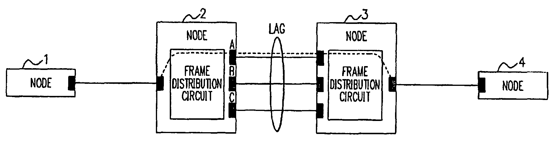
[0034]FIG. 7 shows a configuration of a communication system according to the exemplary embodiment. This communication system includes four nodes 1 to 4, and Link Aggregation is formed for redundancy between nodes 2 and 3. As sections managed by Ethernet OAM, sections between the nodes 1, 2, 3, 4 are assumed. The Ethernet OAM defined in ITU-T Y.1731 is assumed to be used here. MEPs (Maintenance End Points) are set in the nodes 1 and 4 which are ends of the Ethernet OAM. The section between the nodes 2 and 3 is made redundant by the Link Aggregation, and three physical interfaces (lines A, B, C) are connected between the nodes 2 and 3. By an algorithm defined by a frame distribution circuit, a physical connection which is a path of a frame is determined between the nodes 2 and 3 forming the Link Aggregation.

[0035]CC frames are sent from the node 1 to the node 4 as a multicast frame as well as from the node 4 to the node 1 as a multicast frame. At the MEPs at the both ends, abnormalit...

second exemplary embodiment

[0050]A second exemplary embodiment of the present invention will be described.

[0051]FIG. 12 shows a configuration of the frame distribution circuit 20 according to the exemplary embodiment. Although this configuration is mostly the same as in the first exemplary embodiment, it further includes a failure information adding unit 206. The failure information adding unit 206 adds failure information provided as a notification from the CC LAG frame monitoring unit 203, to a CC frame.

[0052]In the exemplary embodiment, if CC LAG frames corresponding to all connection IDs cannot be received within a predetermined time or even if a CC LAG frame having another sequence ID is received before the CC LAG frames corresponding to all the connection IDs are received, the CC LAG frame monitoring unit 203 does not discard a CC frame corresponding to a relevant sequence ID. Instead, the CC LAG frame monitoring unit 203 outputs information about an unreceived CC LAG frame to the failure information ad...


PUM


Abstract

A line status monitoring circuit receives a frame through one of a number of lines from another node connected through a redundant transmission channel which is made redundant by the lines. The line status monitoring circuit includes a line-specific check frame monitoring unit. If a line-specific check frame having an added dedicated header corresponding to each of the plurality of lines is received through one of the lines from another node, the line-specific check frame monitoring unit determines whether or not a further line-specific check frame corresponding to a frame for checking which is identical to a frame for checking to which the line-specific check frame corresponds is received through at least a predetermined number of lines within a predetermined time. If the further line-specific check frame is not received in this manner, the line-specific check frame monitoring unit discards the frame.

Description

[0001]This application is based upon and claims the benefit of priority from Japanese patent application No. 2008-054153, filed on Mar. 4, 2008, the disclosure of which is incorporated herein in its entirety by reference.BACKGROUND OF THE INVENTION[0002]1. Field of the Invention[0003]The present invention relates to a line status monitoring circuit, a node, a communication system, and a failure occurrence determining method which monitor occurrence of failure in a redundant part of a network.[0004]2. Description of the Related Art[0005]A communication system including a redundant part as shown in FIG. 1 is disclosed in Japanese Patent No. 3730824 and Japanese Patent Laid Open Publication No. 2006-262291.[0006]FIG. 2 shows one example of a communication system including a redundant part as in the above patent documents. A case will be described in which CC (Continuity Check) is performed by Ethernet (R) OAM (Operations Administration Maintenance) in the shown communication system. CC...

Claims


Application Information

Patent Timeline
Patent Type & Authority Patents(United States)
IPC IPC(8): H04L1/00H04M3/00H04L12/70H04M3/22
CPCH04L1/0082H04L1/22H04L2001/0097
Inventor KITAJIMA, KATSUYA
Owner NEC CORP
Why Eureka
Try Eureka