
Method for transforming data, and method for transmitting and receiving data using the same

a technology of transforming data and receiving data, applied in the field of transmitting data in a mobile communication system, can solve the problems of limiting the physical channel resources required for reporting cqi, and the difficulty of mimo system in effectively transmitting the increased cqi, so as to minimize the amount of information, effectively use limited wireless resources, and minimize the effect of information

Inactive Publication Date: 2012-02-21
LG ELECTRONICS INC
View PDF18 Cites 8 Cited by
  • Summary
  • Abstract
  • Description
  • Claims
  • Application Information

AI Technical Summary

Benefits of technology

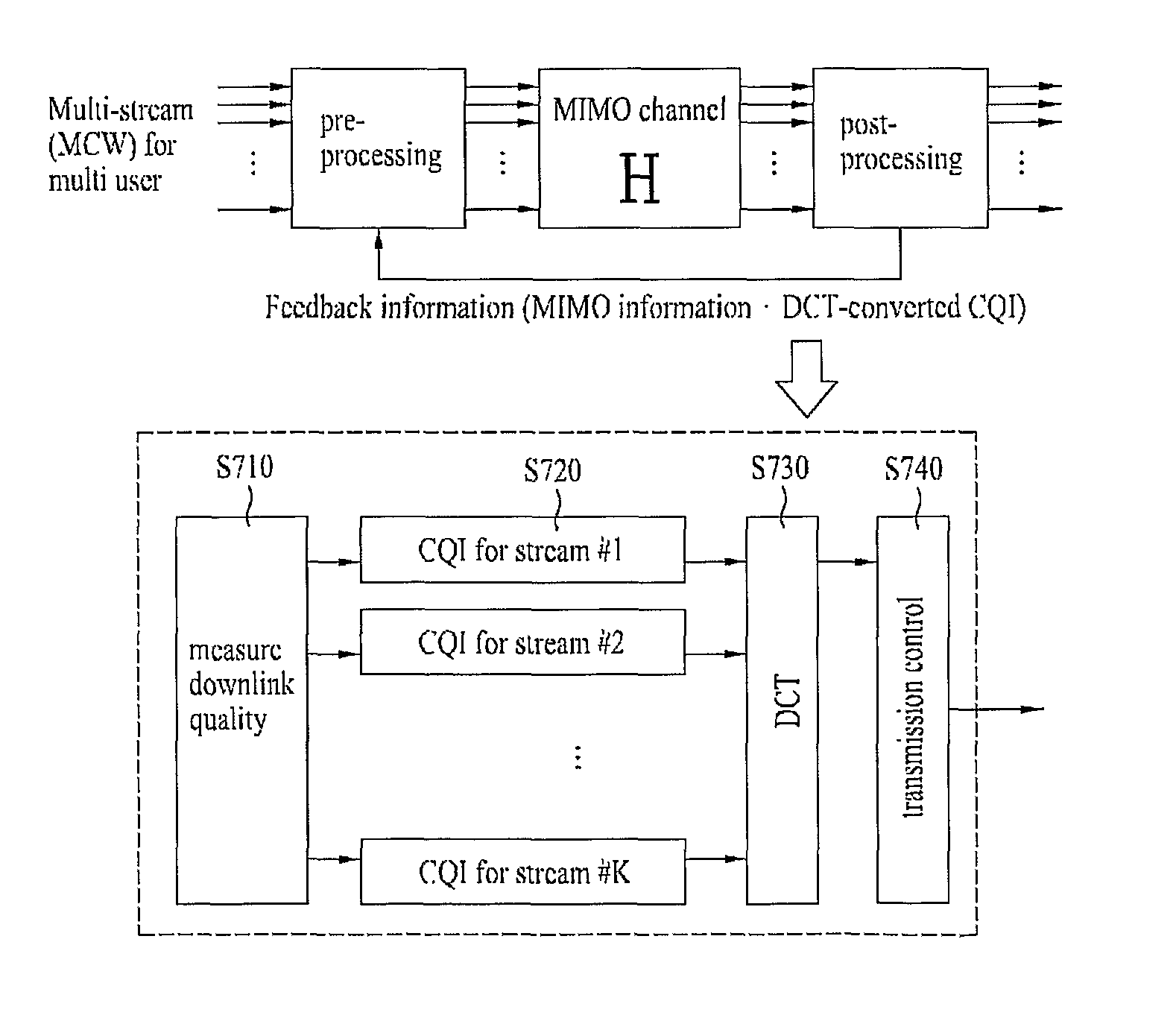
[0024]The present invention minimizes an amount of information to be transmitted to a reception side, transmits the minimized information, and effectively using limited wireless resources. The transmission information may be freely selected, and the present invention can be applied to a variety of technical fields. If the present invention is used to transmit the CQI, it minimizes the performance deterioration of a multi-carrier system, and sufficiently transmits the space-time-variable CQI to the Node-B using a small amount of control information. The DCT is executed on the measured CQI, some parts of the DCT coefficients are transmitted, such that an amount of overhead of feedback information transmitted to the physical channel is minimized, and can properly feed back the CQI according to the channel variation speed.

Problems solved by technology

However, physical channel resources required for reporting the CQI are restricted, such that the MIMO system has difficulty in effectively transmitting the increased CQI.

Method used


Image

  • Method for transforming data, and method for transmitting and receiving data using the same
  • Method for transforming data, and method for transmitting and receiving data using the same
  • Method for transforming data, and method for transmitting and receiving data using the same

Examples


first preferred embodiment

[0173]The first preferred embodiment performs the DM process on the CQI for each CQI band of 2nd to 4th antennas (ant#2˜ant#4) corresponding to the CQI for each CQI band of a first antenna (ant#1, reference antenna).

[0174]FIG. 16 shows data distributed to individual antennas for use in a data transmission method according to a first preferred embodiment of the present invention.

[0175]In this case, if SINR(i)(j) is set to CQI of the j-th CQI band of the i-th antenna, the value DM(Δ(2)(j)) of the second antenna is denoted by Δ(2)(j)=SINR(2)(j)−SINR(1)(j). In this case, the DM process of the 2nd to 3rd antennas may be differentiated by the first antenna as shown in FIG. 16 or may be differentiated by a previous antenna of the first antenna. If the DM process is differentiated by the previous antenna, a multi-antenna demodulator of a successive interference cancellation (SIC) scheme is established, such that this case is very useful to a specific case in which the demodulated SINR value...

second preferred embodiment

[0176]The second preferred embodiment performs the antenna-area DM process of the first preferred embodiment, performs a 2D-DCT (2 Dimensional-Discrete Cosine Transform) process on all the SINR values of overall CQI bands of all the antennas, thereby minimizing an amount of information.

[0177]FIG. 17 shows data distributed to individual antennas for use in a data transmission method according to a second preferred embodiment of the present invention. FIG. 17 shows data distribution for each antenna in the case of the 2D-DCT process of 4×4 units. In this case, the 2D-DCT process is not always limited to the 4×4 units, and a variety of units can be applied to the 2D-DCT process according to communication situation, the number of antennas, and the number of CQI bands, etc.

[0178]The second preferred embodiment is more useful to the case in which the degree of corresponding between frequency bands of individual antennas is high, and when applied to that case, resulting in the minimized co...

third preferred embodiment

[0179]The third preferred embodiment performs the CQI measurement and the antenna-area DM process of the first preferred embodiment a predetermined number of times at intervals of a specific time (e.g., sub-frame of 0.5 ms units), collects the execution results, configures M×N matrix for each antenna, performs the 2D-DCT process on the matrix, and transmits the 2D-DCT result to the reception side. In this case, the size of the matrix may be determined in various ways according to the number of antennas, the number of CQI bands, and the number of unit execution times, etc.

[0180]The UE of the transmission side includes a plurality of buffers corresponding to the number of the execution times, each buffer temporarily stores the result of each execution time.

[0181]If the matrix is implemented with the 4×4 matrix, the matrix for the first antenna is as follows:

[0182]A=[A⁢⁢1A⁢⁢2A⁢⁢3A⁢⁢4]⁢⁢B=[B⁢⁢1B⁢⁢2B⁢⁢3B⁢⁢4]⁢⁢C=[C⁢⁢1C⁢⁢2C⁢⁢3C⁢⁢4]

[0183]FIG. 18 shows data distributed to individual antennas...


PUM


Abstract

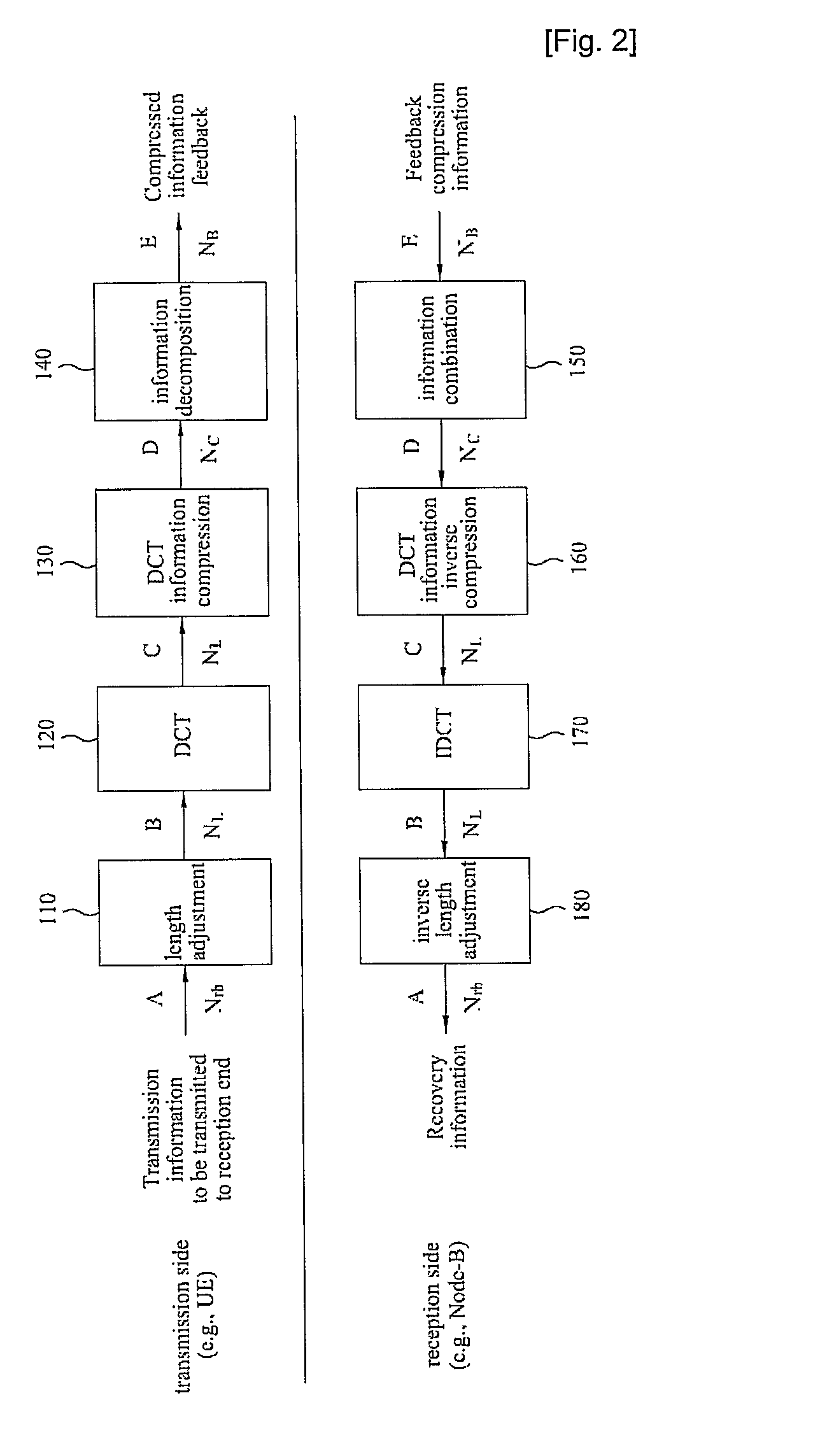
A method for transforming data to reduce an amount of data in a communication system equipped with several sub-carriers, and a data transmission method using the same are disclosed. The method for transmitting data using a Discrete Cosine Transform (DCT) in a communication system based on a plurality of sub-carriers includes: a) performing a Discrete Cosine Transform (DCT) on first data; b) selecting a predetermined number of data from among the DCT-processed first data, and performing data processing on the selected data; and c) transmitting the data-processed resultant data to a reception end. A method for reducing an amount of overhead of transmission data for use in the multi-antenna communication system is disclosed.

Description

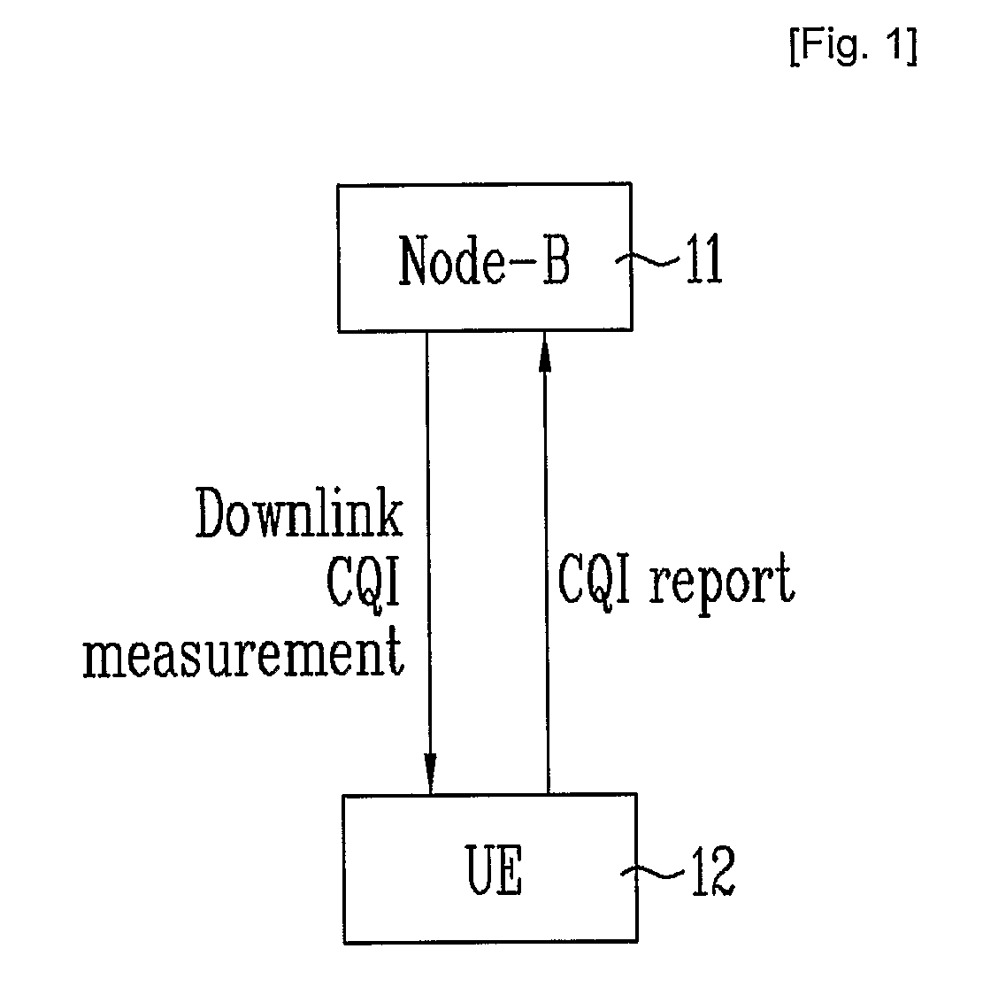
CROSS-REFERENCE TO RELATED APPLICATIONS[0001]This application is the National Stage filing under 35 U.S.C. of International Application No. PCT / KR2007 / 001326, filed on Mar. 19, 2007, which claims the benefit of earlier filing date and right of priority to Korean Patent Application Nos. 10-2006-0039579, filed on May 2, 2006, 10-2006-0051443, filed on Jun. 8, 2006, 10-2006-0097400, filed on Oct. 2, 2006, and 10-2007-0001079, filed on Jan. 4, 2007, and also claims the benefit of U.S. Provisional Application Ser. Nos. 60 / 783,739, filed on Mar. 17, 2006, and 60 / 827,872, filed on Oct. 2, 2006.TECHNICAL FIELD[0002]The present invention relates to a method for transmitting data in a mobile communication system, and more particularly to a data transmission method for processing data on information to be transmitted, thereby minimizing an amount of the information.BACKGROUND ART[0003]FIG. 1 is a conceptual diagram illustrating an uplink data reporting method for use in a mobile communication ...

Claims


Application Information

Patent Timeline
Patent Type & Authority Patents(United States)
IPC IPC(8): H04L27/28H04B7/02
CPCH04B7/0417H04B7/0632H04L1/0026H04L1/0029H04L1/0656H04L1/0003H04L1/0009H04L1/16H04L5/0023H04L5/0091H04L5/023H04L27/2602H04L1/0023
Inventor YUN, YOUNG WOOKIM, HAK SEONGKIM, BONG HOEAHN, JOON KUISEO, DONG YOUNLEE, JUNG HOONKIM, KI JUNYOON, SUK HYONKIM, EUN SUNLEE, DAE WON
Owner LG ELECTRONICS INC
Learn More