Allograft intervertebral implant and method of manufacturing the same

a technology of intervertebral implants and manufacturing methods, which is applied in the field of intervertebral implants, can solve the problems of inability to manufacture implants, limited lateral placement of implants, severe back pain, etc., and achieve the effect of facilitating spinal fusion

Active Publication Date: 2012-03-06
SYNTHES USA
View PDF4 Cites 143 Cited by
  • Summary
  • Abstract
  • Description
  • Claims
  • Application Information

AI Technical Summary

Problems solved by technology

A number of medical conditions such as, for example, compression of spinal cord nerve roots, degenerative disc disease, herniated nucleus pulposus, spinal stenosis and spondylolisthesis can cause severe back pain.
The T-PLIF procedure avoids damage to nerve structures such as the dura, cauda equina and the nerve root, but the resulting transforaminal window available to remove the affected disc, prepare the vertebral endplates, and insert the implant is limited laterally by soft tissue and medially by the cauda equina.
However, because of the interlocking surfaces and pins, the intervertebral implant is formed as a solid body implant (e.g., the implant does not contain any through bore for receiving bone graft material).
That is, because of the complexities of forming and machining implants from allograft bone as compared to forming and machining implants from a metal, polymer, etc., manufacturers have been unable to manufacture implants sized and configured for PLIF and T-PLIF procedures that include one or more through bores for receiving bone graft material to facilitate bone fusion.
Moreover, known multi-piece allograft implants are generally initially joined together and then the joined pieces are shaped, this may result in less control and in reduced size potential.

Method used


Image

  • Allograft intervertebral implant and method of manufacturing the same
  • Allograft intervertebral implant and method of manufacturing the same
  • Allograft intervertebral implant and method of manufacturing the same

Examples


Embodiment Construction

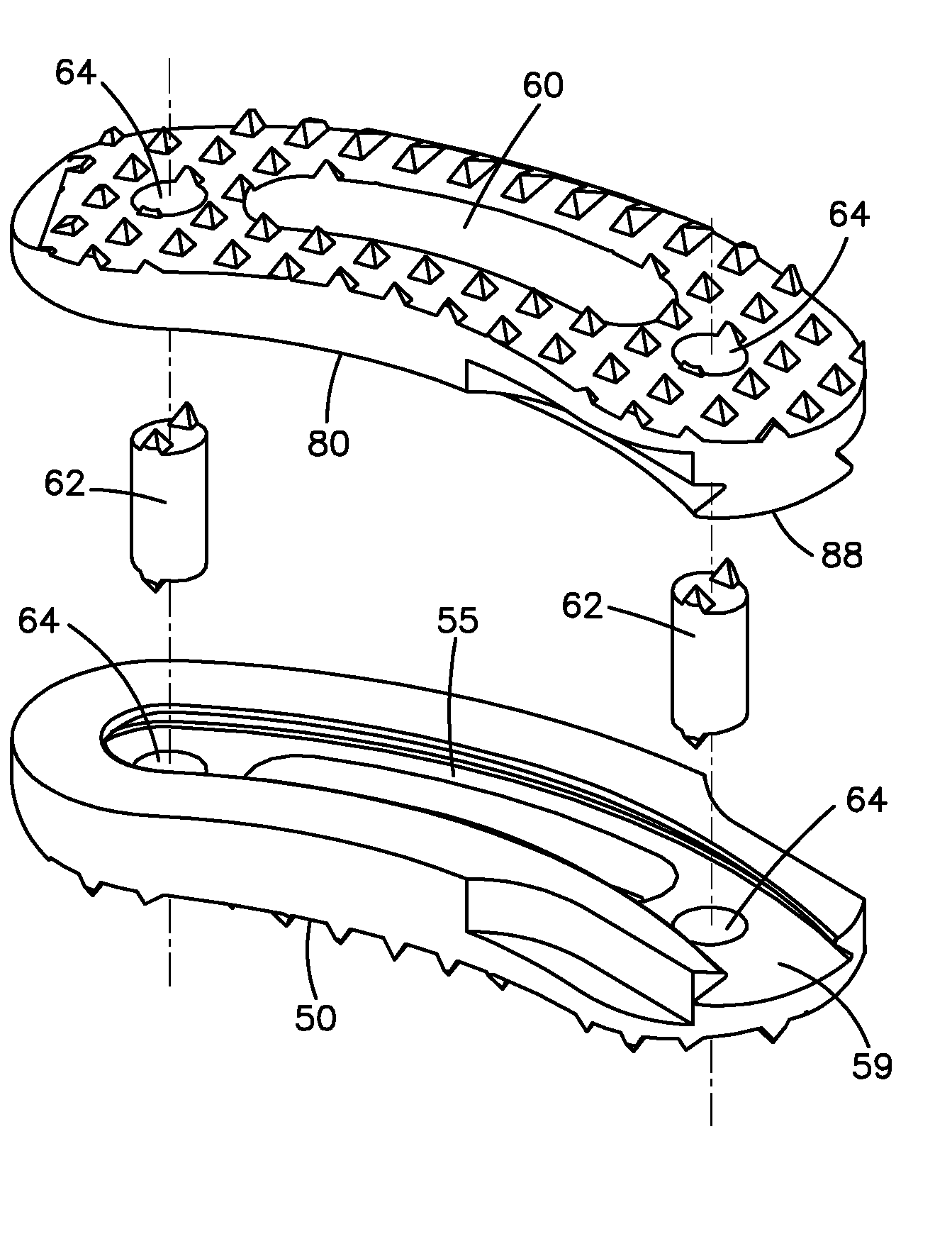
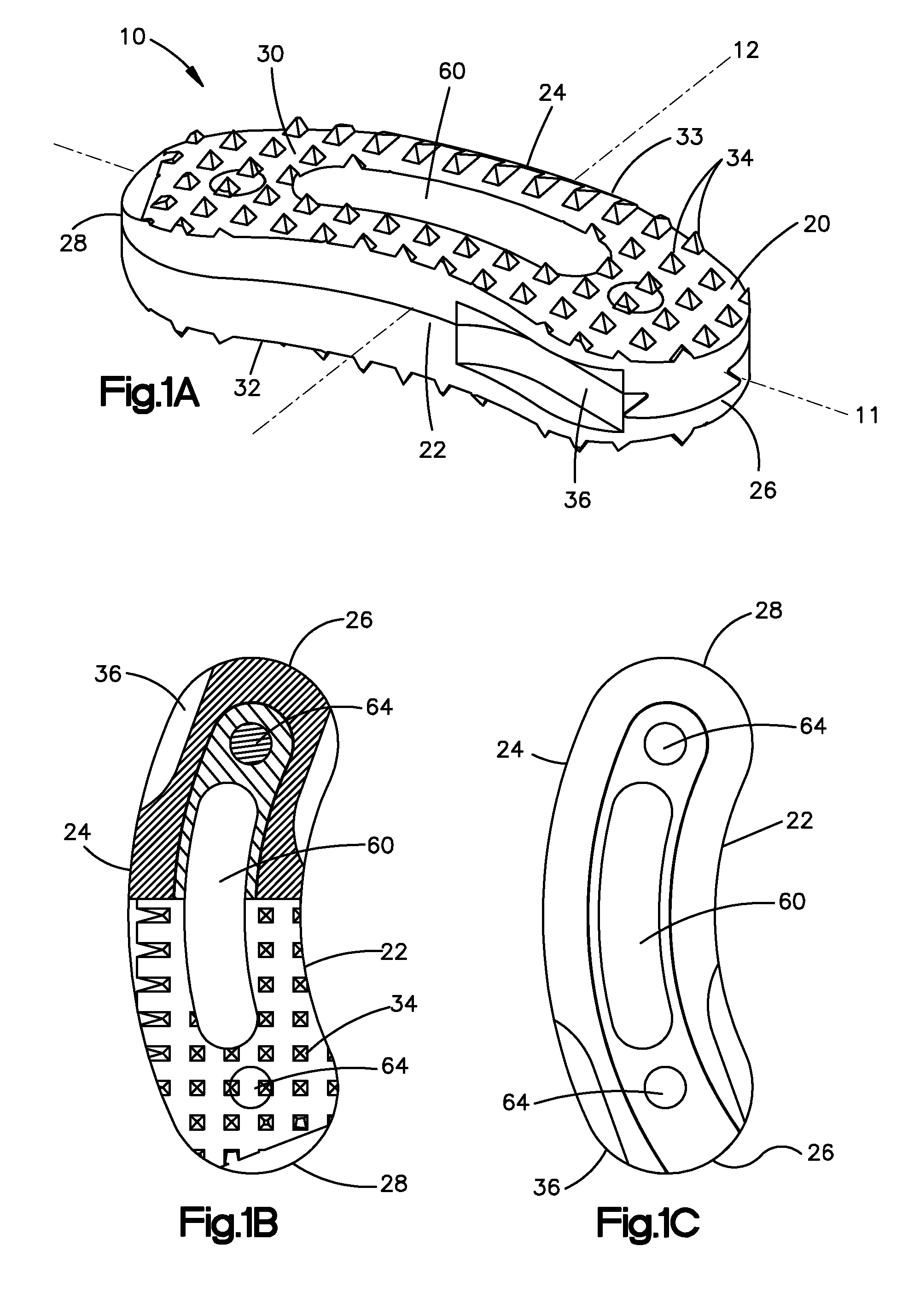
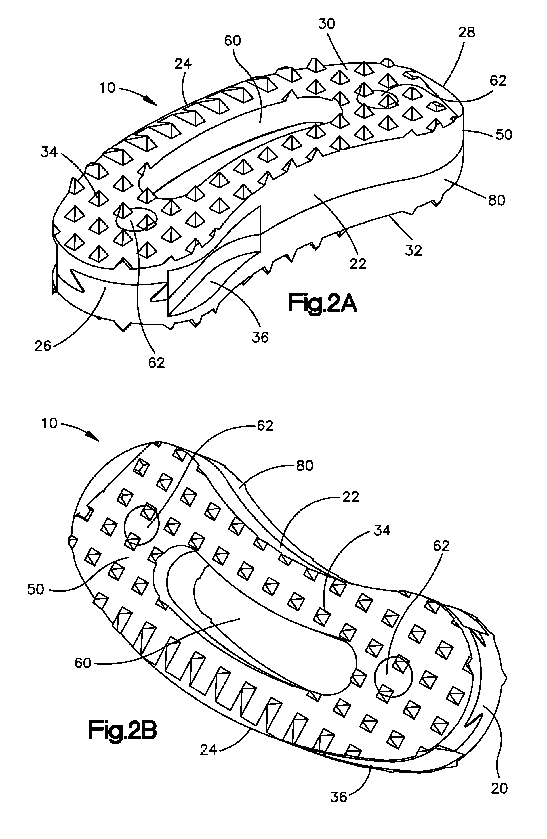
[0048]Certain exemplary embodiments of the invention will now be described with reference to the drawings. In general, such embodiments relate to an intervertebral implant for insertion between adjacent vertebral bodies to restore vertebrae spacing wherein the implant is sized and configured for use as an intervertebral spacer in a spinal fusion surgery, wherein an affected disk is removed from between two adjacent vertebrae and replaced with the implant. The implant preferably provides segmental stability and allows for bone to grow in-between the two adjacent vertebrae to bridge the gap created by disk removal. By way of non-limiting example, the intervertebral implant may be made from two or more pieces of allograft bone. The invention may have other applications and uses and should not be limited to the structure or use described and illustrated. As will be described in greater detail below, the intervertebral implant may include two or more pieces of allograft bone joined toget...


PUM

PropertyMeasurementUnit
lengthaaaaaaaaaa
widthaaaaaaaaaa
heightaaaaaaaaaa

Abstract

The present invention is directed to an allograft intervertebral implant sized and configured for insertion between adjacent vertebral bodies in a spinal fusion surgery. The implant is preferably manufactured from two or more pieces of allograft bone joined together by a joint, more preferably a dovetail joint. The dovetail joint being sized and configured to substantially follow the exterior shape or surface (e.g. perimeter) of the intervertebral implant. The intervertebral implant may also include one or more bone pins for joining the allograft pieces, the pins being inserted into the implant at an angle substantially perpendicular with respect to the dovetail joint. The intervertebral implant may also include one or more through-bores for receiving ostegenic or bone graft material. The intervertebral implant is preferably sized and configured for insertion during a T-PLIF or PLIF procedure.

Description

CROSS REFERENCE TO RELATED APPLICATION[0001]This application claims the benefit of U.S. Provisional Application No. 60 / 844,515 filed Sep. 13, 2006, the entire content of which is expressly incorporated herein by reference thereto.FIELD OF THE INVENTION[0002]The present invention is directed to an intervertebral implant, more particularly to an intervertebral implant made from two or more pieces of allograft bone.BACKGROUND OF THE INVENTION[0003]A number of medical conditions such as, for example, compression of spinal cord nerve roots, degenerative disc disease, herniated nucleus pulposus, spinal stenosis and spondylolisthesis can cause severe back pain. Intervertebral fusion is one surgical method for alleviating back pain. In a posterior lumbar interbody fusion (“PLIF”) procedure, two adjacent vertebral bodies are fused together by removing the affected intervertebral disc and inserting posteriorly one or more implants on either side of the midline of the spine that would allow fo...

Claims


Application Information

Patent Timeline
Patent Type & Authority Patents(United States)
IPC IPC(8): A61F2/44
CPCA61F2/4465A61F2/4644A61F2/447A61F2/28Y10T29/4998A61F2/4611A61F2002/2835A61F2002/30133A61F2002/30387A61F2002/30492A61F2002/30772A61F2002/30841A61F2002/4629A61F2220/0025A61F2230/0015A61F2310/00359A61F2/3094
Inventor DELURIO, ROBERT J.WALSH, RYANMCMANUS, JOSHUA
Owner SYNTHES USA
Why Eureka
Try Eureka