Joint-space impedance control for tendon-driven manipulators

a tendon-driven manipulator and joint-space technology, applied in the field of system and method control of tendon-driven manipulators, can solve the problems of robotic manipulator undesired motion and extra control burden

Active Publication Date: 2011-11-15
NASA +1
View PDF41 Cites 960 Cited by
  • Summary
  • Abstract
  • Description
  • Claims
  • Application Information

AI Technical Summary

Problems solved by technology

However, this presents an extra control burden because the resulting physical coupling between tendons and joints must be decoupled in the control system.
Thus, undesired motions occur in the robotic manipulator.

Method used


Image

  • Joint-space impedance control for tendon-driven manipulators
  • Joint-space impedance control for tendon-driven manipulators
  • Joint-space impedance control for tendon-driven manipulators

Examples


Embodiment Construction

[0014]The following discussion of the embodiments of the invention directed to a system and method for controlling tendon-driven manipulators is merely exemplary in nature, and is in no way intended to limit the invention or its applications or uses.

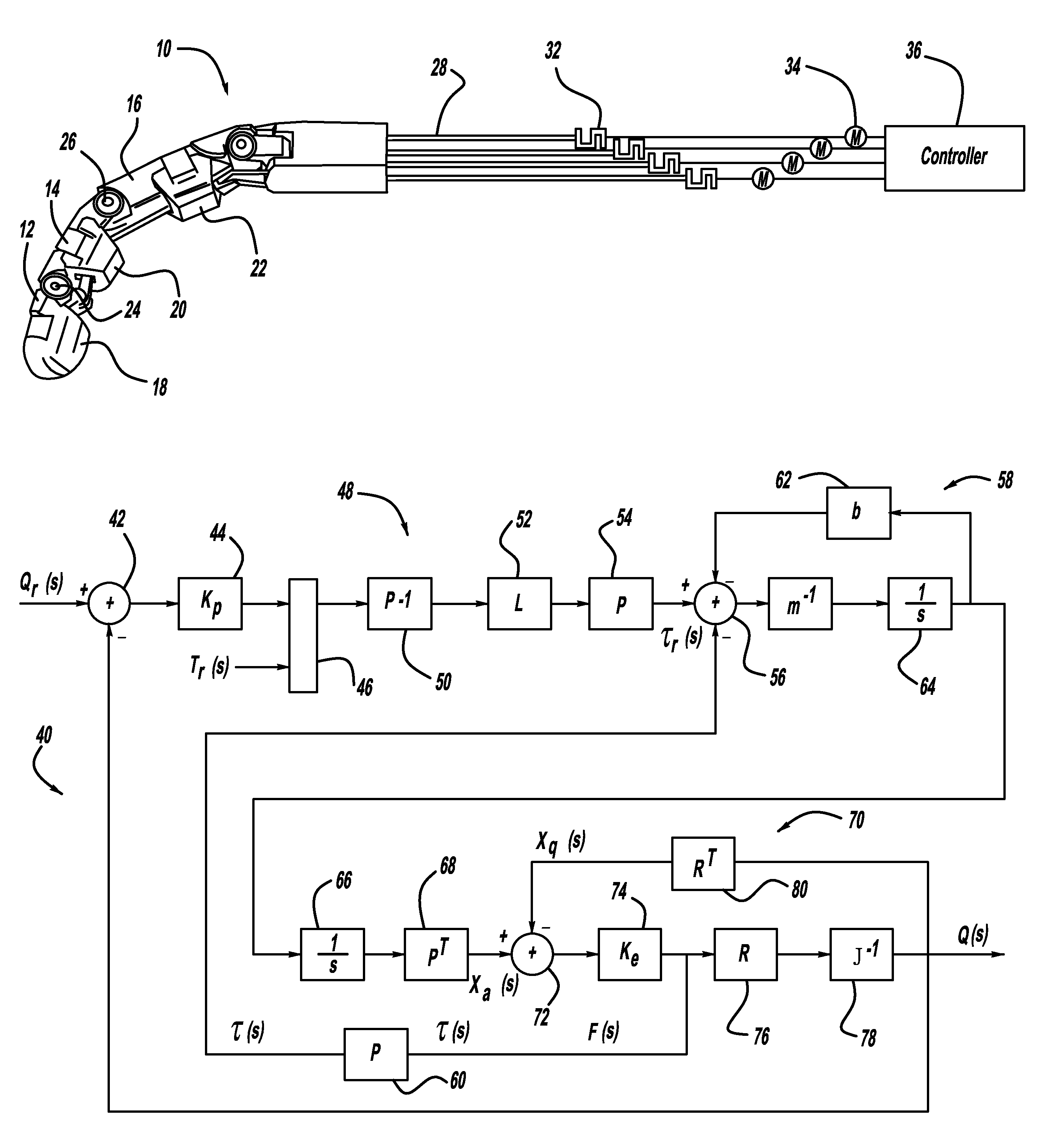
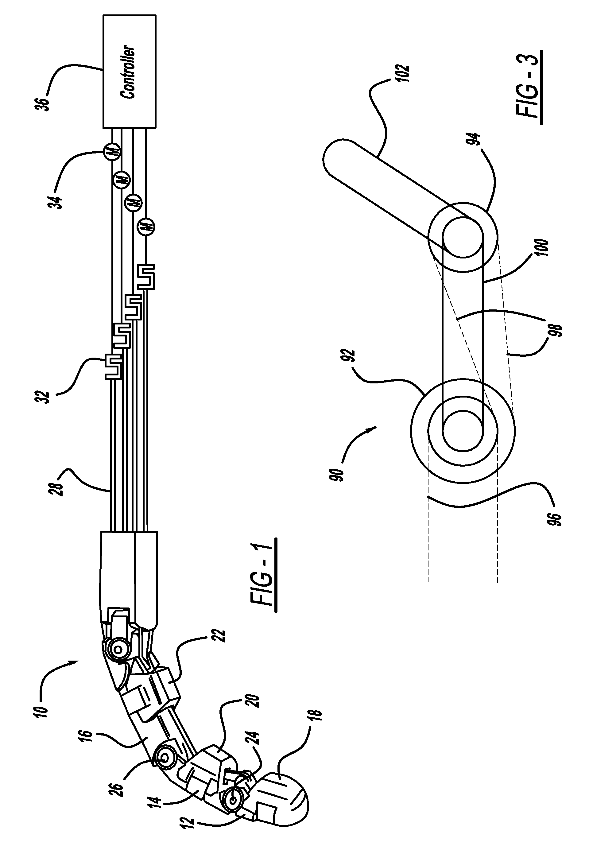
[0015]The following embodiments apply the present invention to the control of a tendon-actuated finger. However, the present invention can be applied to any tendon-driven robot manipulator. Consider the perspective view of a robotic finger 10 for a robotic arm shown in FIG. 1. The robotic finger 10 includes three finger sections, namely, a tip section 12, an intermediate section 14 and a base section 16. The tip section 12 includes a pad 18, the intermediate section 14 includes a pad 20 and the base section 16 includes a pad 22 that allow the finger 10 to effectively grasp a particular part (not shown). The finger sections 12, 14 and 16 and the pads 18, 20 and 22 can be made of any suitable material, such as aluminum, for a particular ap...


PUM


Abstract

A system and method for controlling tendon-driven manipulators that provide a closed-loop control of joint torques or joint impedances without inducing dynamic coupling between joints. The method includes calculating tendon reference positions or motor commands by projecting a torque error into tendon position space using a single linear operation. The method calculates this torque error using sensed tendon tensions and a reference torque and internal tension. The method can be used to control joint impedance by calculating the reference torque based on a joint position error. The method limits minimum and maximum tendon tensions by projecting the torque error into the tendon tension space and then projecting ii back into joint space.

Description

STATEMENT REGARDING FEDERALLY SPONSORED RESEARCH OR DEVELOPMENT[0001]The invention described herein may be manufactured and used by or for the U.S. Government for U.S. Government (i.e., non-commercial) purposes without the payment of royalties thereon or therefore.BACKGROUND OF THE INVENTION[0002]1. Field of the Invention[0003]This invention relates generally to a system and method for controlling a tendon-driven manipulator using closed-loop control. In particular, the joint angle and torque in the joints of the manipulator are controlled in such a way that it reduces coupled transient joint motions and allows for independent motion of the joints.[0004]2. Discussion of the Related Art[0005]Dexterous robot systems typically comprise robot arms and hands that operate to grasp and manipulate objects or parts during assembly or other applications. The term “robot manipulator” is used to describe all or part of one or more robot arms and hands. Tendon-driven robot manipulators are robot...

Claims


Application Information

Patent Timeline
Patent Type & Authority Patents(United States)
IPC IPC(8): G06F19/00
CPCB25J9/1633G05B2219/39457
Inventor REILAND, MATTHEW J.PLATT, ROBERTWAMPLER, II, CHARLES W.ABDALLAH, MUHAMMAD E.HARGRAVE, BRIAN
Owner NASA
Why Eureka
Try Eureka