Image display control apparatus and method

a control apparatus and image technology, applied in the direction of printers, cameras, instruments, etc., can solve the problem of inability to realize efficient confirmation of regions

Active Publication Date: 2012-03-06
CANON KK
View PDF6 Cites 13 Cited by
  • Summary
  • Abstract
  • Description
  • Claims
  • Application Information

AI Technical Summary

Benefits of technology

[0008]An embodiment of the present invention provides an image display control apparatus which can display separately extracted regions in such a manner as enabling those regions to be efficiently confirmed.
[0010]With an embodiment of the present invention, a user can efficiently confirm the separately extracted regions.

Problems solved by technology

When those regions are independently confirmed without taking into account correlation between the regions as in the related art, efficient confirmation of the regions cannot be realized.

Method used


Image

  • Image display control apparatus and method
  • Image display control apparatus and method
  • Image display control apparatus and method

Examples


Embodiment Construction

[0040]An exemplary embodiment of the present invention will be described in detail below with reference to the accompanying drawings.

[0041]It is to be noted that the following exemplary embodiment is merely one example for implementing the present invention and can be appropriately modified or changed depending on individual constructions and various conditions of apparatuses to which the present invention is applied. Thus, the present invention is in no way limited to the following exemplary embodiment.

(Construction of Digital Camera)

(a) External Appearance

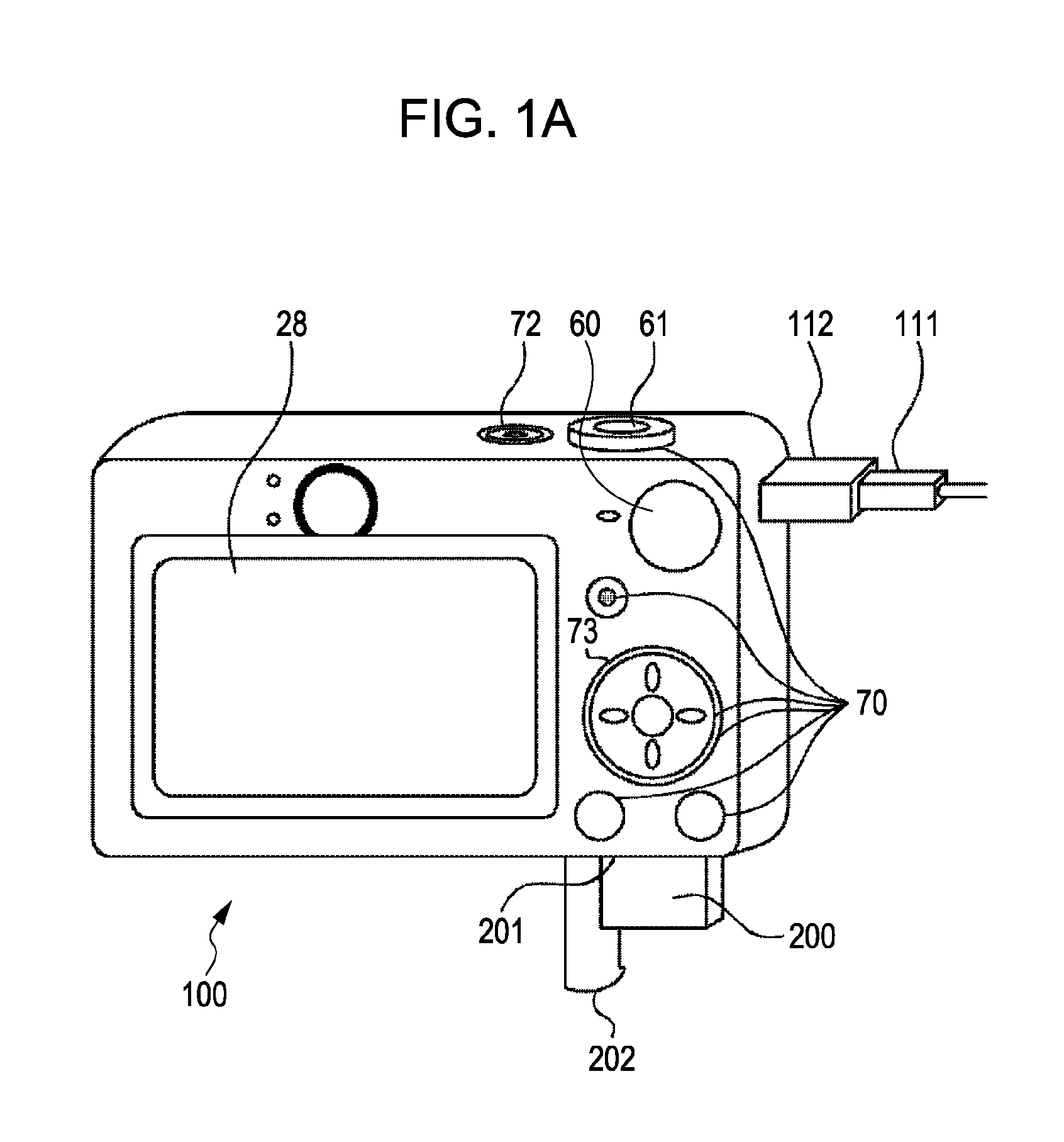
[0042]FIG. 1A is an external appearance view of a digital camera as an example of an image display control apparatus according to an exemplary embodiment of the present invention. In FIG. 1A, a display unit 28 displays an image and various items of information. A power switch 72 switches over power-on and power-off. Numeral 61 denotes a shutter button. A zoom lever is disposed outside the shutter button 61. A mode selector switch...


PUM


Abstract

A degree of overlapping between separately obtained regions of respective parts of an image is determined. When the degree of overlapping is greater than a defined value, only one of the obtained regions, or both the regions, or a region including both the regions is selected. When the degree of overlapping is less than the defined value, the separately obtained regions of respective parts of the image are separately selected. The image is displayed while reflecting a result of the selection.

Description

BACKGROUND OF THE INVENTION[0001]1. Field of the Invention[0002]The present invention relates to an image display control apparatus and method adapted to display an image, and also relates to a recording medium in which a program is recorded.[0003]2. Description of the Related Art[0004]Recently, techniques have been proposed to display frames serving various purposes, each frame corresponding to a region of an image. For example, an in-focus frame represents a region of an image which has selected for focus adjustment at the time of shooting the image, and a face frame indicating a region of an image where a face has been detected by an image analysis, in an superimposed relation to the image and / or in an enlarged size.[0005]For example, Japanese Patent Laid-Open No. 2005-295418 describes the following technique. An object and an in-focus frame are displayed in an overlapped relation at the time of shooting, and a region of the in-focus frame in an image is displayed in an enlarged ...

Claims


Application Information

Patent Timeline
Patent Type & Authority Patents(United States)
IPC IPC(8): G09G5/00G03B13/18
CPCH04N5/23219H04N5/23293H04N23/61H04N23/611H04N23/635
Inventor SUDO, KOJINIWA, CHIYUMIYOSHIDA, NOBUKAZU
Owner CANON KK
Why Eureka
Try Eureka