Automatic firing pin block safety for a firearm

a technology of automatic firing pin and safety mechanism, which is applied in the direction of breech mechanism, small arms, ammunition loading, etc., can solve the problems of difficult installation within the frame of the firearm, complex mechanism, and accidental discharge of certain prior art firearms, and achieve the effect of enabling operation

Active Publication Date: 2012-03-13
SMITH & WESSON
View PDF210 Cites 28 Cited by
  • Summary
  • Abstract
  • Description
  • Claims
  • Application Information

AI Technical Summary

Benefits of technology

[0011]It is an object of the present invention to provide an automatic firing pin block safety mechanism that controllably blocks the firing pin from moving into contact with a chambered round and is actuated by the trigger.
[0013]It is an object of the present invention to provide an automatic firing pin block safety mechanism that disables the operation of a firearm incorporating such a device is disabled when the firing pin is, in effect, taken out of engagement with a chambered round of ammunition unless and until the trigger is moved rearward. This is true even if the sear is actuated or the hammer is rotated before then. However, rearward movement of the trigger automatically causes the flange-like safety element to unblock the firing pin, meaning that the user does not have to manually disengage the automatic firing pin block safety prior to discharging the firearm.

Problems solved by technology

For example, certain prior art firearms can experience an accidental discharge if dropped, particularly, on the rear portion of the firearm.
However, such firing pin safeties can involve complex mechanism and are difficult to install within the frame of the firearm.
Although the aforesaid devices can be effective, they generally are so effective at disabling the firearm that it can be awkward to re-activate the firearm.
The process of pinning the sight in place can be a time consuming step of the manufacture of a firearm.

Method used


Image

  • Automatic firing pin block safety for a firearm
  • Automatic firing pin block safety for a firearm
  • Automatic firing pin block safety for a firearm

Examples


Embodiment Construction

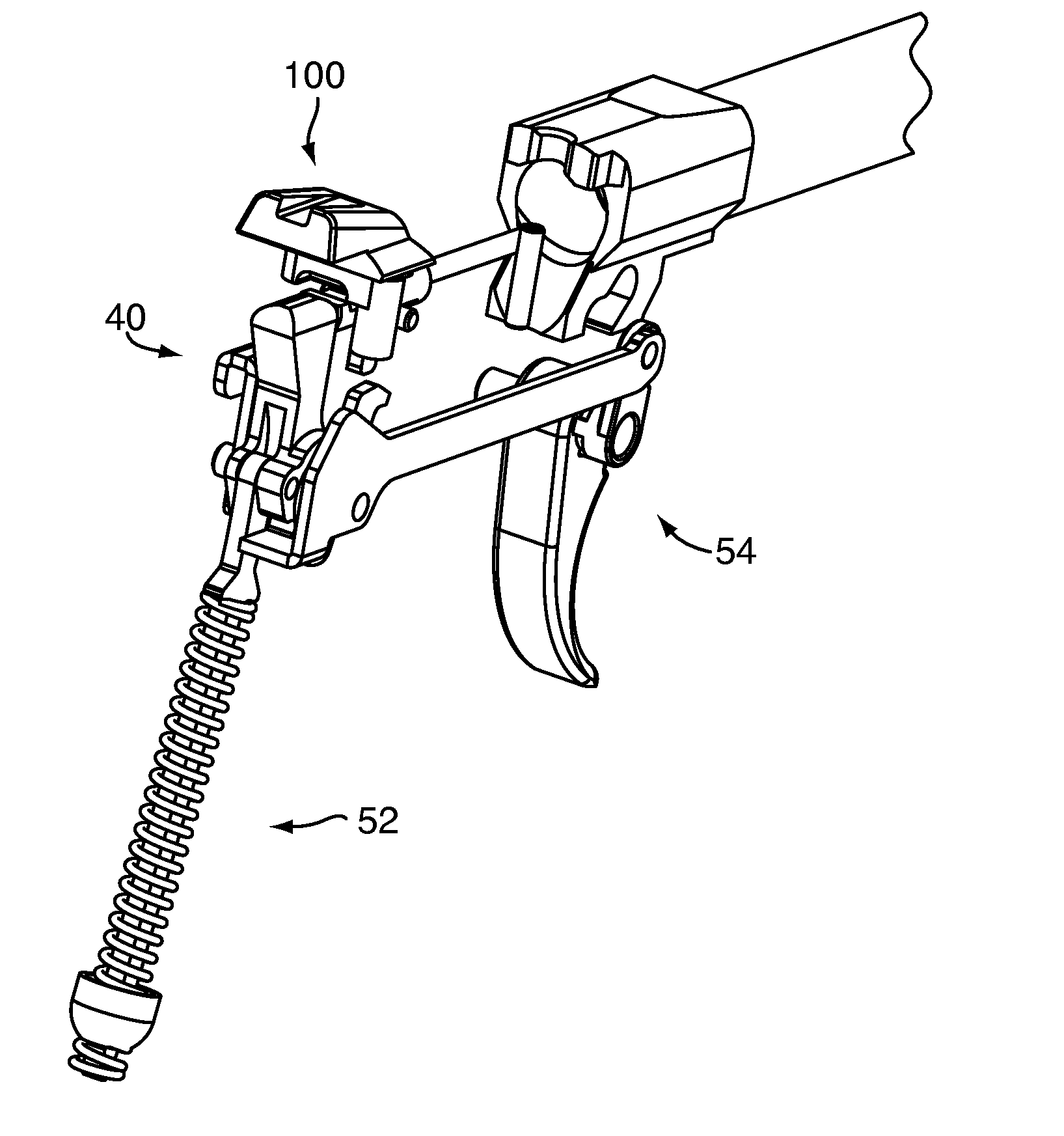
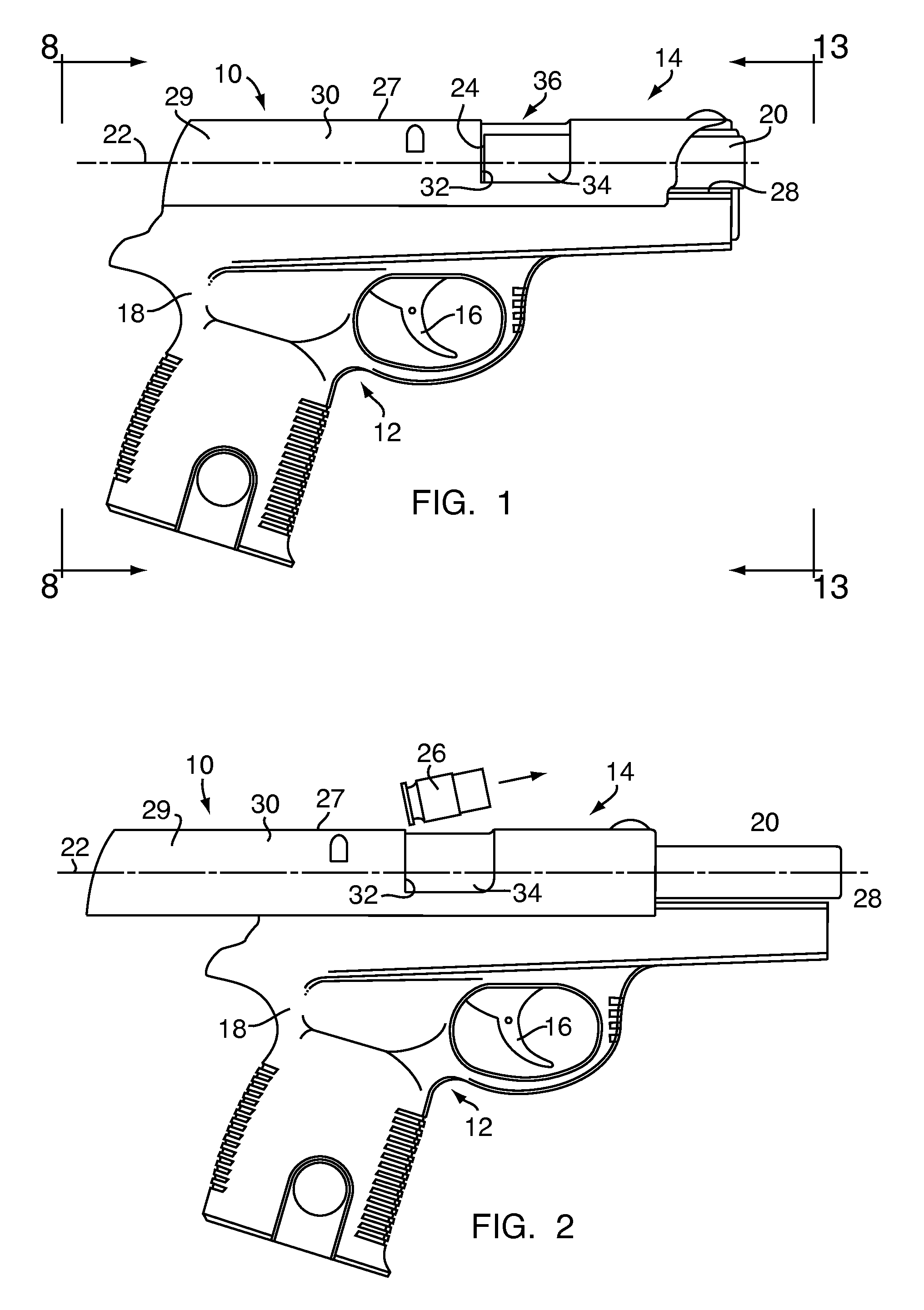
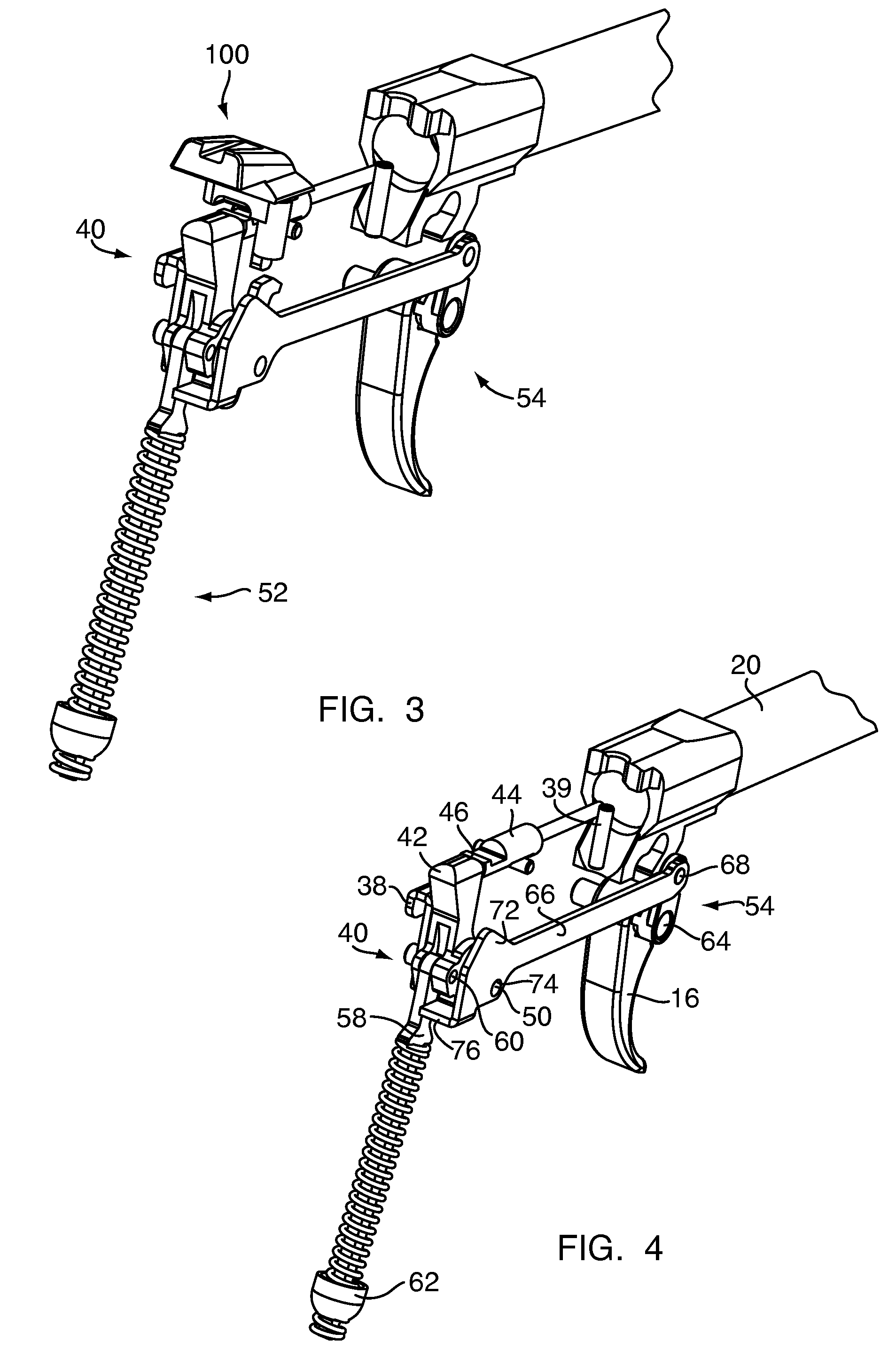
[0031]FIGS. 1 and 2 show one example of a firearm, handgun or semi-automatic pistol (hereinafter referred to as “firearm 10”) that may incorporate an automatic firing pin block safety mechanism 100, a manual slide and hammer lock safety mechanism 200, and a configurable sight 300 according to an embodiment of the present invention. The firearm 10 includes a frame 12, a slide 14, a trigger 16, an automatic firing pin block safety mechanism 100 (hereinafter referred to as “automatic safety 100”) (see FIGS. 3-8) that operates via actuation of the trigger 16, a manual slide and hammer lock and hammer lock safety mechanism 200 (hereinafter referred to as “manual safety 200”) (see FIGS. 9-11) that operates via actuation of a rotatable tab 202 and a configurable sight 300 (see FIGS. 12-13) that removably connects to the slide 14. The frame 12 includes a grip body 18 for holding the firearm 10 and is fabricated of a high-impact polymer material, metal, a combination of polymer and metal, or...


PUM

PropertyMeasurementUnit
shapeaaaaaaaaaa
timeaaaaaaaaaa
distanceaaaaaaaaaa

Abstract

A firearm has a frame, a trigger, a trigger bar, a hammer-type firing mechanism including a hammer having a hammer pin connected to the trigger via the trigger bar and a firing pin, and an automatic firing pin block safety mechanism (“automatic safety”) including a flange that is spring biased into engagement with the firing pin and a pivot lock arm rotatably mounted to the hammer pin and releasable engageable with the flange. The flange blocks the firing pin from discharging a chambered round unless and until the trigger is positively actuated. The automatic safety reduces the risk of accidental discharge, thereby rendering the firearm safer.

Description

CROSS REFERENCE TO RELATED APPLICATIONS[0001]This application claims the benefit of U.S. Provisional Application Ser. No. 61 / 141,503, filed on Dec. 30, 2008, herein incorporated by reference in its entirety. This application is related to U.S. Non-Provisional application Ser. No. 12 / 650,124 entitled A MANUAL SLIDE AND HAMMER LOCK SAFETY FOR A FIREARM filed on Dec. 30, 2009, and U.S. Non-Provisional application Ser. No. 12 / 650,217 entitled A CONFIGURABLE SIGHT FOR A FIREARM filed on Dec. 30, 2009, herein incorporated by reference in their entirety.FIELD OF THE INVENTION[0002]The present invention relates generally to an automatic safety for a firearm and more particularly to an automatic firing pin block safety mechanism for a semi-automatic pistol.BACKGROUND OF THE INVENTION[0003]Fire control mechanisms used in semi-automatic firearms oftentimes utilize hammer-initiated firing pins. In firearms that employ this design, the trigger is connected to a trigger bar. Movement of the trigg...

Claims


Application Information

Patent Timeline
Patent Type & Authority Patents(United States)
IPC IPC(8): F41A17/26
CPCF41A17/66Y10T29/49908
Inventor ZUKOWSKI, GARY
Owner SMITH & WESSON
Why Eureka
Try Eureka