Methods for centering optical fibers inside a connector ferrule and optical fiber connector

a technology of optical fiber and connector ferrule, which is applied in the direction of optics, instruments, optical light guides, etc., can solve the problems of significant amounts of optical fiber not fitting into the bore, the difficulty of achieving such exact alignment, and the difficulty of centering one or more optical fibers in a single-fiber or multi-fiber connector ferrul

Inactive Publication Date: 2012-03-13
CORNING OPTICAL COMM LLC
View PDF3 Cites 40 Cited by
  • Summary
  • Abstract
  • Description
  • Claims
  • Application Information

AI Technical Summary

Problems solved by technology

However, achieving such exact alignment has proven to be difficult.
One reason why centering one or more optical fibers in a single-fiber or multi-fiber connector ferrule is difficult is because it is not practical to use an interference fit between an optical fiber and a ferrule bore.
Optical fibers can vary in size by up to ±1 micron or so, so that sizing a ferrule bore to have an interference fit with the optical fiber would result in significant amounts of optical fiber not fitting into the bore.
In addition, those optical fibers that can barely be fit into the bore have a higher risk of being damaged due to the tight fit.

Method used


Image

  • Methods for centering optical fibers inside a connector ferrule and optical fiber connector
  • Methods for centering optical fibers inside a connector ferrule and optical fiber connector
  • Methods for centering optical fibers inside a connector ferrule and optical fiber connector

Examples


Embodiment Construction

[0044]Reference is now made to preferred embodiments of the invention, examples of which are illustrated in the accompanying drawings. Whenever possible, the same or similar reference numbers and symbols are used throughout the drawings to refer to the same or similar parts.

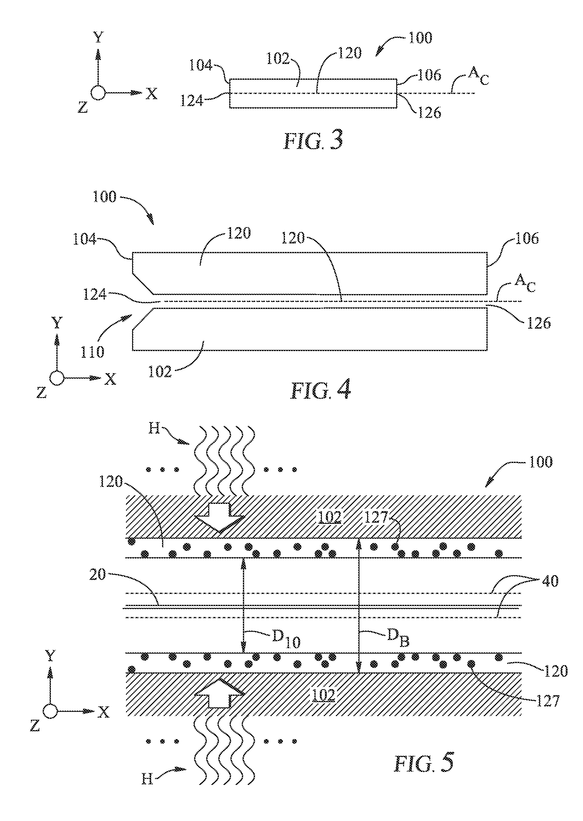
[0045]In the description below, the term “void-free” in connection with an optical fiber means that there are no voids visible when the fiber end face is viewed at a magnification of 400× using an optical microscope. The smallest feature that is visible at such magnification is about 0.4 μm in diameter, so that any voids smaller than this size may be present, but would not be considered sufficiently large to be of significance in relation to the performance of the fiber. The term “substantially void free” means that there may be present voids having diameter of 0.4 μm or greater, but the number of voids (i.e., the air-fill percent) is so reduced as compared to that prior to thermally processing the fiber that the...


PUM


Abstract

Methods for centering at least one optical fiber (10) having a centerline (16) in a connector ferrule (100) having at least one bore (120) with a central axis (AC) is disclosed. One method includes inserting a bare-fiber portion (13) into a ferrule bore so that at least a section (10S) of the bare-fiber portion extends beyond the ferrule front end (106). The method also includes selectively applying an amount of energy to the bare-fiber section to form a locally deformable region (19), and forming at a bulge (250) in the locally deformable region. The method also includes causing the bulge to form a force-fit with the bore at the ferrule front end, thereby substantially centering the optical fiber centerline along the bore central axis. Methods of centering nano-engineered optical fibers are also disclosed, wherein the optical fiber end is processed so that a substantially void-free fiber end (14) is made to substantially coincide with the ferrule front end. Methods directed to multiple optical fibers and multifiber ferrules are also disclosed.

Description

CROSS-REFERENCE TO RELATED APPLICATIONS[0001]This application is related to (a) U.S. patent application Ser. No. 11 / 595,365, entitled “Method of splicing an optical fiber with holes in the cladding,” filed in the United States on Nov. 9, 2007; (b) U.S. patent application Ser. No. 12 / 077,694, entitled “Connectorized nano-engineered optical fibers and methods of forming same,” filed in the United States on Mar. 20, 2008; and (c) U.S. patent application Ser. No. 12 / 220,266, entitled “Connectorized nano-engineered optical fibers and methods of forming same,” filed in the United States on Jul. 23, 2008, all of which are incorporated by reference herein.BACKGROUND OF THE INVENTION[0002]1. Field of the Invention[0003]The present invention relates generally to optical fibers and optical fiber connectors, and more specifically to methods for centering one or more optical fibers in an optical fiber connector ferrule.[0004]2. Technical Background of the Invention[0005]With the ever growing dem...

Claims


Application Information

Patent Timeline
Patent Type & Authority Patents(United States)
IPC IPC(8): G02B6/26G02B6/255G02B6/42G02B6/38G02B6/36
CPCG02B6/3834G02B6/02342G02B6/02366G02B6/3847G02B6/3861G02B6/403
Inventor LUTHER, JAMES P.MILLER, DARRIN M.
Owner CORNING OPTICAL COMM LLC
Why Eureka
Try Eureka