
Safety device for securing minimum spaces at the top or bottom of an elevator shaft being inspected, and elevator having such safety devices

a safety device and elevator technology, applied in the field of elevators, can solve the problems of fork elements, unexpectedly remaining in the retracted position, and affecting the safety of personnel entering the hoistway, and achieve the effect of preventing the fork from falling o

Inactive Publication Date: 2012-03-20
OTIS ELEVATOR CO
View PDF30 Cites 13 Cited by
  • Summary
  • Abstract
  • Description
  • Claims
  • Application Information

AI Technical Summary

Benefits of technology

[0011]The position sensor makes it possible to check that the retractable element is well deployed prior to allowing movement of the car in the inspection operation. This avoids the risk that a mechanic controlling an upward or downward movement of the car from inside the shaft may lose the protection afforded by the safety device.
[0018]An advantage of such a configuration of the safety device is that two levels of safety can be provided relatively close to each other for the same direction of travel of the car by means of two retractable elements. The spring arrangement allows the two elements to slide together along a relatively long stroke which may be needed for the safety brake to effectively stop the car, thus eliminating the problem that the support of one of the two elements may hinder the vertical sliding of the other element when it is hit by the triggering member of the safety brake.
[0027]The actuator is advantageously controlled to put the retractable element in the stopping position when the elevator is in an inspection operation. The position sensor is coupled to the elevator control circuit to prevent movement of the car in the inspection operation when the retractable element is not in the stopping position.

Problems solved by technology

A problem with this kind of safety device is that the fork element may, for various reasons, become jammed and unexpectedly remain in the retracted position when an inspection operation is started.
This creates a danger for the personnel entering the hoistway.

Method used


Image

  • Safety device for securing minimum spaces at the top or bottom of an elevator shaft being inspected, and elevator having such safety devices
  • Safety device for securing minimum spaces at the top or bottom of an elevator shaft being inspected, and elevator having such safety devices
  • Safety device for securing minimum spaces at the top or bottom of an elevator shaft being inspected, and elevator having such safety devices

Examples


Embodiment Construction

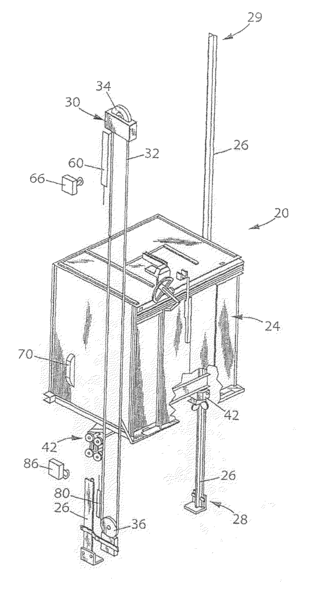
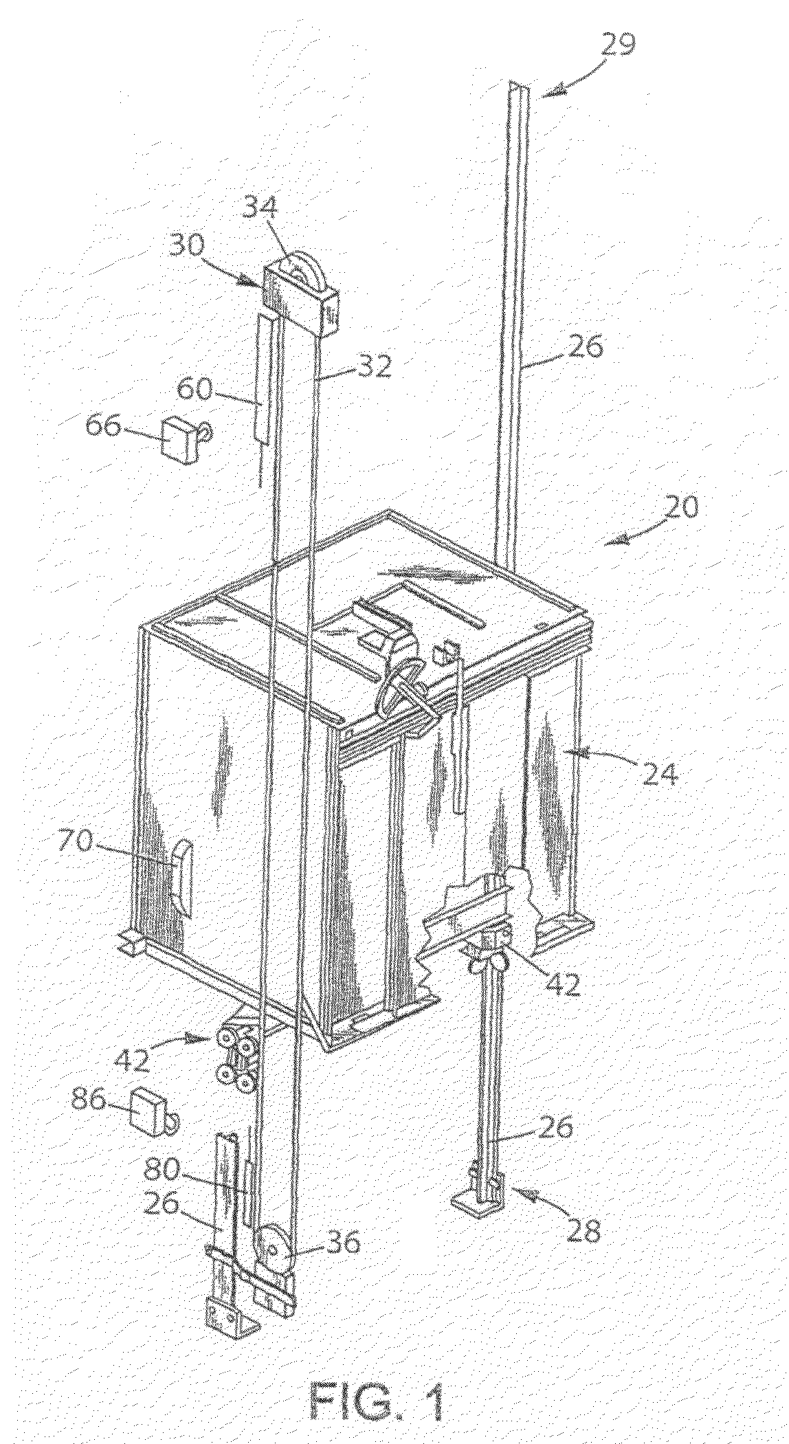
[0041]FIG. 1 shows an elevator system 20 including an elevator car 24 that moves along guide rails 26 in a known manner.

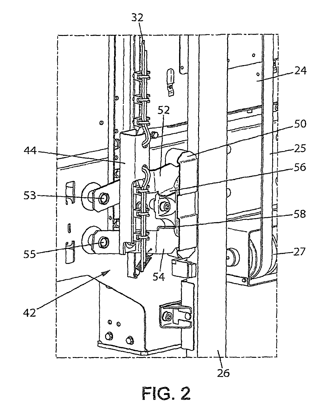
[0042]In one example, a machine room-less elevator system allows the car 24 to move essentially along the entire length of a hoistway between a lower end 28 (i.e. a pit) and an upper end 29 of a hoistway. A drive system (not shown) including a motor and a brake is conventionally used to control the vertical movements of the car 24 along the hoistway via a traction system partly visible in FIG. 2, including cables or belts 25 and reeving pulleys 27.

[0043]In addition, a governor device 30 controls movement of the car 24 by preventing it from moving beyond a selected maximum speed. The example governor device 30 includes a governor rope 32 that travels with the car 24 as the car moves along the guide rails 26. A governor sheave 34 and a tension sheave 36 are at opposite ends of a loop followed by the governor rope 32.

[0044]The illustrated governor device 30 operates i...


PUM


Abstract

A safety device for an elevator system includes a retractable element mounted on a support. The retractable element has a stopping position in which a catch portion of the retractable element projects from the support to engage a triggering member of a safety brake associated with an elevator car as the elevator car traveling in a selected direction approaches a selected vertical position, and a retracted position. An actuator selectively controls the position of the retractable element. A position sensor is responsive to the position of the retractable element to make sure that it is in its stopping position when needed.

Description

BACKGROUND OF THE INVENTION[0001]The present invention relates to elevators. It applies, in particular, to elevators having a shallow pit and / or a low overhead.[0002]Elevators with a shallow pit and / or a low overhead are advantageous because of the reduced impact of their installation on the construction cost and because of their compatibility with severe architectural constraints.[0003]Machine room-less elevators have their drive system, in particular their motor and brake, located inside the volume of the elevator shaft. Access to these parts, and to other components fitted in the shaft is required for maintenance or repair purposes. Standards such as EN81 require safety clearances at the top and at the bottom of the shaft so that a person can enter a safe working space to have access to the machines and shaft components. Such working space can be located in the upper part of the hoistway, with the operator standing on top of the car, or in the pit at the bottom of the shaft.[0004...

Claims


Application Information

Patent Timeline
Patent Type & Authority Patents(United States)
IPC IPC(8): B66B1/34
CPCB66B5/0068B66B5/18B66B13/22
Inventor COQUERELLE, THOMASBEAUCHAUD, FREDERICFONTENEAU, NICOLASGOULET, DOMINIQUEDUKACZ, OLIVIERSIRIGU, GERARDREBILLARD, PASCAL
Owner OTIS ELEVATOR CO
Learn More