System for making renewable fuels

a renewable fuel and fuel technology, applied in the field of renewable fuel systems, can solve the problems of inherently inefficient process, large amount of resultant compounds, and inability to meet the needs of industrial production,

Inactive Publication Date: 2012-03-20
COOL PLANET ENERGY SYST
View PDF56 Cites 39 Cited by
  • Summary
  • Abstract
  • Description
  • Claims
  • Application Information

AI Technical Summary

Problems solved by technology

This is inherently a very inefficient process.
Although some pyrolyzers are focused simply on producing syngas, there is considerable effort in the development of milder pyrolyzing conditions, which typically results in a condensed liquid commonly called bio-oil or pyrolysis oil.
The fundamental problem with the resultant pyrolysis oil is that is made up of hundreds to thousands of compounds, which are the result of subjecting the raw biomass to a wide range of temperature, time, and pressure profiles in bulk.
When this process is complicated by the thousands of major bio-compounds in the original bio-feedstock, the result is a nearly intractable array of resultant compounds all mixed together.
Pyrolysis oils from such processes are typically not thermodynamically stable.
Also, attempts to re-gasify pyrolysis oil typically result in additional chemical reactions, which produce additional biochar and a shift to lower molecular weight components in the resulting gas stream.
Although fairly high yields of pyrolysis oil can be achieved in laboratory scale experiments, larger industrial scale demonstration projects typically produce much lower yield.

Method used


Image

  • System for making renewable fuels
  • System for making renewable fuels
  • System for making renewable fuels

Examples


example 1

Illustrative Example 1

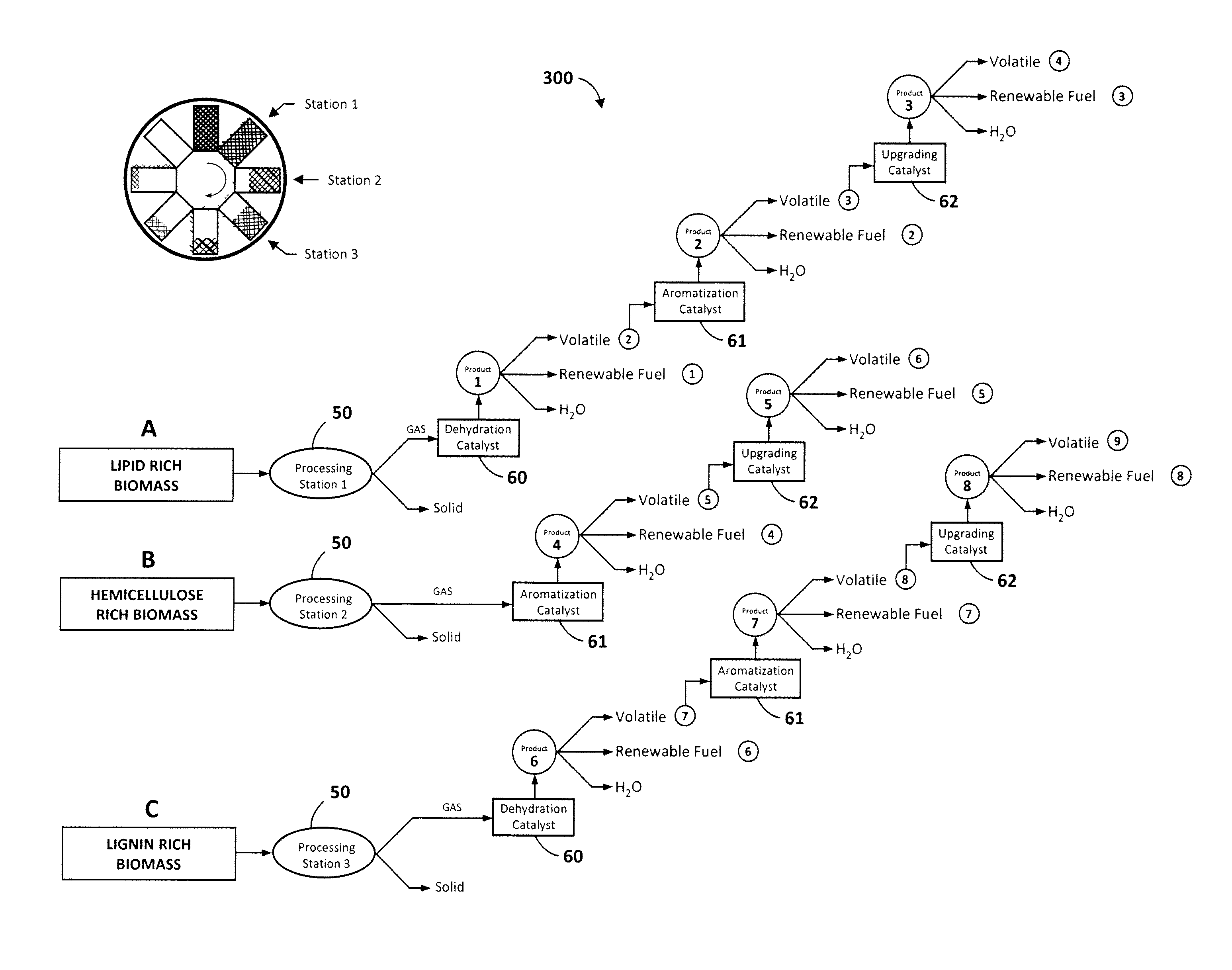
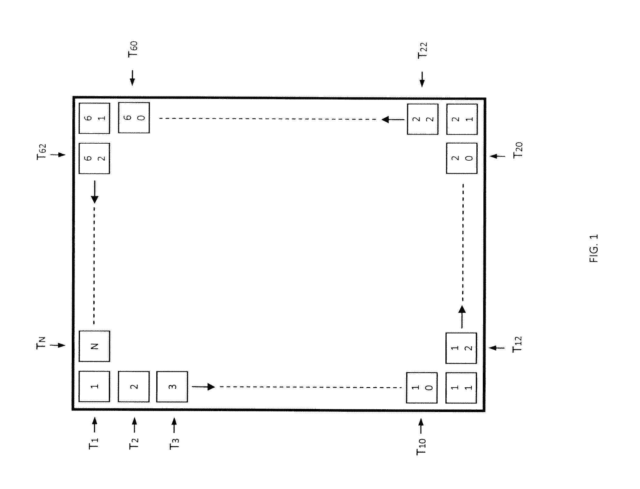
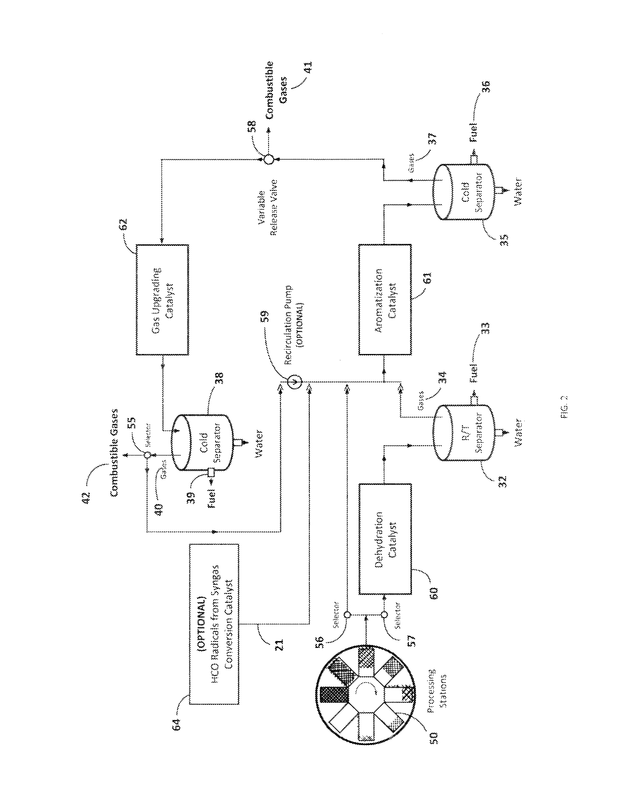
[0047]Referring now to FIG. 6A, this illustrative example is the equivalent to six processing stations 50 operating at six different temperatures wherein the input biomass is fed at 325° C. and the final carbonaceous solid is removed at 575° C. 150 g of biomass consisting of commercial sunflower seeds along with dimethyl ether as co-solvent were devolatilized starting at a temperature of 325° C. and ending at 575° C. with a temperature increment of 50° C. for every hour. 131 g of methanol was passed through a silica alumina catalyst to generate the required co-solvent. The output was passed through three different catalyst columns in series including a dehydration catalyst 60, an aromatization catalyst 61, and a gas-upgrading catalyst 62 as illustrated in FIG. 3 for cut A. More particularly, this experiment employed a silica alumina dehydration catalyst, a Zn and Cr modified ZSM-5 aromatization catalyst, and a Ga modified ZSM-5 gas-upgrading catalyst. FIG. 6A i...

example 2

Illustrative Example 2

[0049]This illustrative example is the equivalent to six processing stations operating at six different temperatures wherein the input biomass is again fed at 325° C. and the final carbonaceous solid is removed at 525° C. 76 g of biomass consisting of commercial corn cobs along with 100 g of methanol were devolatilized starting at a temperature of 325° C. and ending at 525° C. with a temperature increment of 50° C. for every hour. This example assumes that corn cobs contain significant amounts of hemicellulose (C5 sugars), which may decompose in the presence of a dehydration catalyst 60, leading to more breakage of chemical bonds than necessary. Therefore, the output was passed through two different catalyst columns in series, one consisting of an aromatization catalyst 61, followed by a gas-upgrading catalyst 62 as illustrated in FIG. 3 for cut B. In this example, ZSM-5 was employed as the aromatization catalyst, and Ga modified ZSM-5 was employed as the gas-u...

example 3

Illustrative Example 3

[0050]This illustrative example is the equivalent to six processing stations operating at six different temperatures wherein the input biomass is again fed at 325° C. and the final carbonaceous solid is removed at 575° C. 100 g of biomass consisting of red fir wood along with 131 g of methanol were devolatilized starting at a temperature of 325° C. and ending at 575° C. with a temperature increment of 50° C. for every hour. This example assumes that red fir contains significant amounts of lignins which are needed to be decomposed for efficient biomass conversion. The output was passed through two different catalyst columns in series, beginning with the dehydration catalyst 60, and followed by an aromatization catalyst 61. This experiment utilized silica alumina as the dehydration catalyst, and Zn and Cr modified ZSM-5 as the aromatization catalyst. A total of 30.5 ml of renewable fuel was collected by the end of the run from the aromatization catalyst 61, where...


PUM

PropertyMeasurementUnit
temperatureaaaaaaaaaa
particle sizeaaaaaaaaaa
temperatureaaaaaaaaaa

Abstract

Multiple catalytic processing stations couple with a system which produces volatile gas streams from biomass decomposition at discrete increasing temperatures. These catalytic processing stations can be programmed to maximize conversion of biomass to useful renewable fuel components based on input feedstock and desired outputs.

Description

TECHNICAL FIELD[0001]The present invention relates generally to systems for making renewable fuels, and more particularly to the thermal chemical conversion of biomass to renewable fuels and other useful chemical compounds, including gasoline and diesel, via a series of catalysts using a programmable system.DESCRIPTION OF THE RELATED ART[0002]As the world continues to run through its precious resources of fossil fuels, it is going to be forced to turn to other sources of energy. Present global objectives include getting energy cheaply and quickly. Through the ages, mankind has turned to biomass to furnish energy in terms of heat by burning wood and other biomass. This is inherently a very inefficient process. Combustion may be made more efficient by introducing programmability. It is similar to introducing computers to a building that needs to be heated. In order to heat the building only when the person is present, one places a sensor in the building so that the heater turns on whe...

Claims


Application Information

Patent Timeline
Patent Type & Authority Patents(United States)
IPC IPC(8): G05D23/00B01J8/04B01J8/00B01J19/00G05B1/00B01J8/02B01J35/02
CPCC10G1/002C10G2300/1014C10G2300/4006C10G2300/44Y02P30/20
Inventor CHEIKY, MICHAELMALYALA, RAJASHEKHARAM
Owner COOL PLANET ENERGY SYST
Why Eureka
Try Eureka