
System and method for modeling movement of objects using probabilistic graphs obtained from surveillance data

a technology of probabilistic graphs and surveillance data, applied in the field of surveillance systems and object tracking methods, can solve the problems of increasing the computational burden of the surveillance system, the inability to observe objects with cameras, and the inability to use conventional surveillance systems. to achieve the effect of eliminating all ambiguities

Inactive Publication Date: 2012-04-03
MITSUBISHI ELECTRIC RES LAB INC
View PDF6 Cites 16 Cited by
  • Summary
  • Abstract
  • Description
  • Claims
  • Application Information

AI Technical Summary

Benefits of technology

[0005]In a conventional surveillance system, tracking of objects, such as people, animals and vehicles, is usually performed by means of image and video processing. The disadvantage of such a surveillance system is that when a specific object needs to be tracked and identified, the object needs to be observed by a camera. However, many surveillance environments require a large number of video cameras to provide the complete coverage necessary for accurate operation. A large number of video streams increase the computational burden on the surveillance system in order to operate accurately.
[0006]The embodiments of the invention provide a mixed modality surveillance system. The system includes a large number of relatively simple sensors and a relatively small number of movable cameras. This reduces cost, complexity, network bandwidth, storage, and processing time when compared with conventional surveillance systems.
[0008]The embodiments also provide a method and system for modeling and predicting the movement of the objects by determining probabilities to the tracks. As a distinguishing feature, the invention does not require perfect tracks before analysis. Most prior art surveillance tracking systems require a reliable pre-processing step. This implies high-fidelity sensors and computationally complex methods to eliminate all ambiguities.

Problems solved by technology

The disadvantage of such a surveillance system is that when a specific object needs to be tracked and identified, the object needs to be observed by a camera.
However, many surveillance environments require a large number of video cameras to provide the complete coverage necessary for accurate operation.
A large number of video streams increase the computational burden on the surveillance system in order to operate accurately.
This is virtually impossible with conventional surveillance systems that need to search a huge amount of video data.
This implies high-fidelity sensors and computationally complex methods to eliminate all ambiguities.

Method used


Image

  • System and method for modeling movement of objects using probabilistic graphs obtained from surveillance data
  • System and method for modeling movement of objects using probabilistic graphs obtained from surveillance data
  • System and method for modeling movement of objects using probabilistic graphs obtained from surveillance data

Examples


Embodiment Construction

[0020]Surveillance System

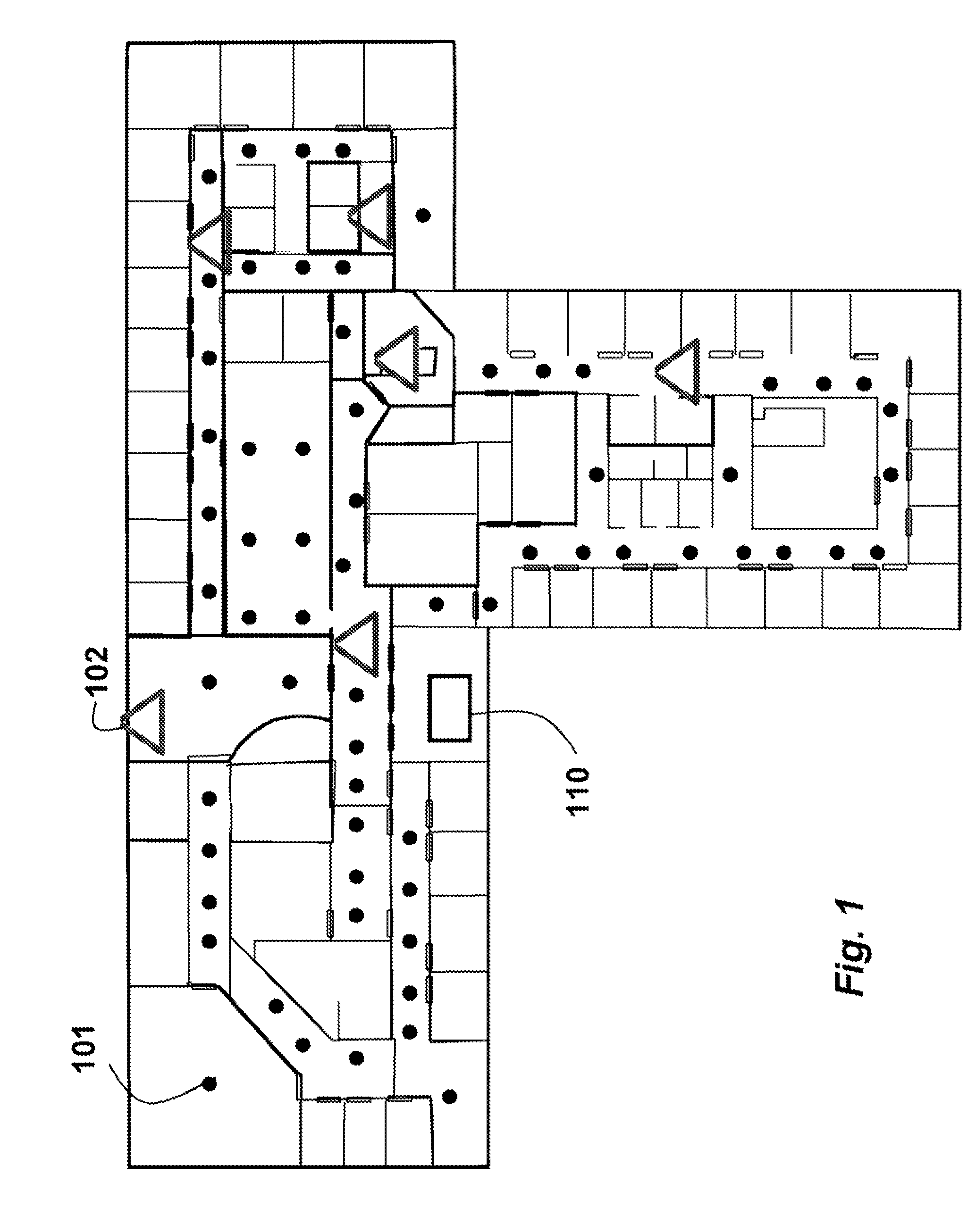
[0021]As shown in FIG. 1, a surveillance system in which, a tracking module is implemented according to the embodiments of our invention includes a relatively large set of wireless network of sensors (dots) 101 and relatively small set of pan-tilt-zoom (PTZ) cameras (triangles) 102. The ratio of sensors to cameras can be very large, e.g., 30:1, or larger.

[0022]Sensors

[0023]The sensors can be motion sensors, and door, elevator, heat, pressure and acoustic sensors. Motion sensors, such as infra red sensors, can detect the movement of objects in a vicinity of the sensor. Door sensors can detect door opening and closing events, typically indicative of a person passing through the doorway. Elevator sensors can similarly indicate the arrival or departure of people in an environment. Acoustic sensors, e.g., transducers and microphones, can also detect activity in an area. Sensors can be mounted on light switches, or power switches of office equipment in the environ...


PUM


Abstract

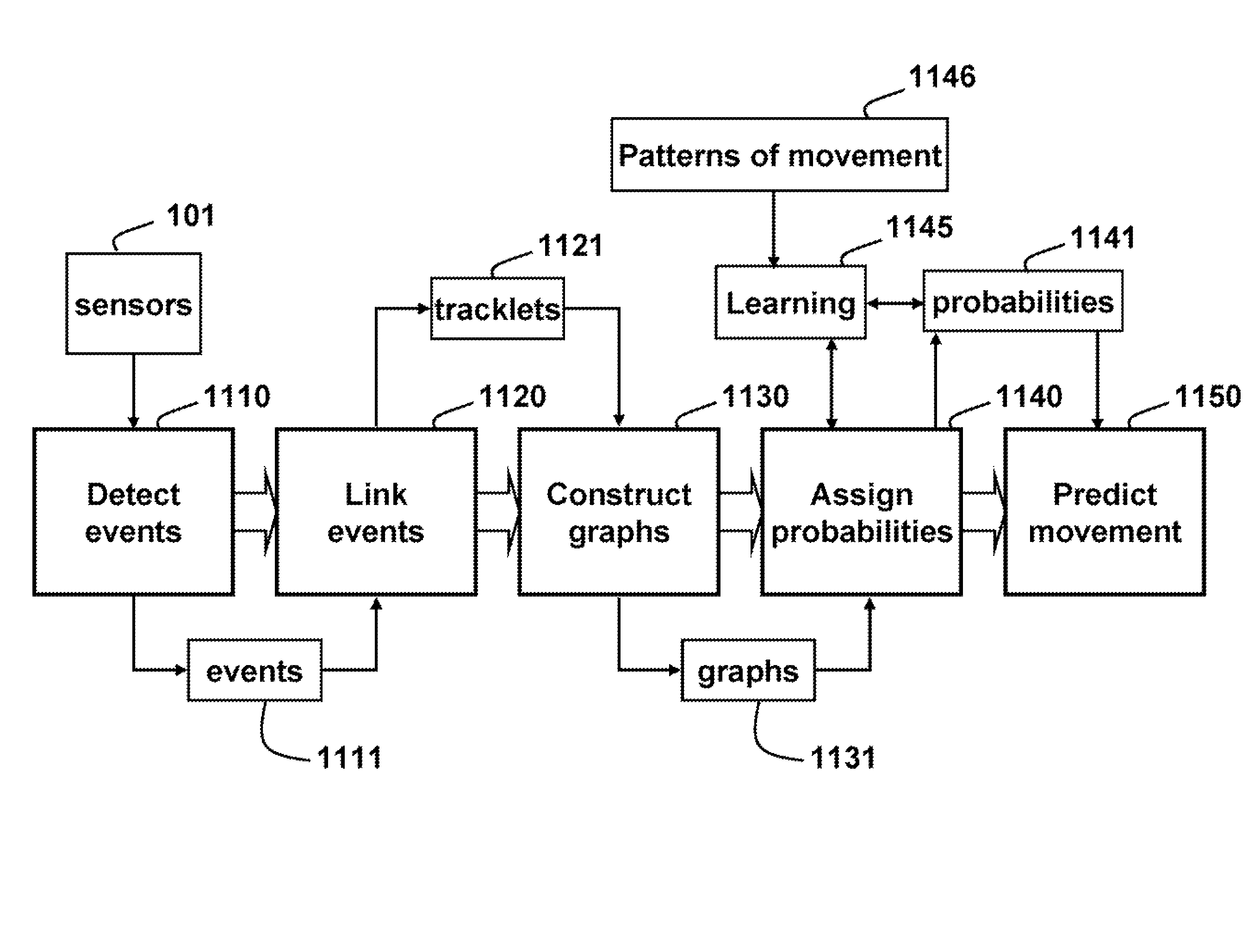
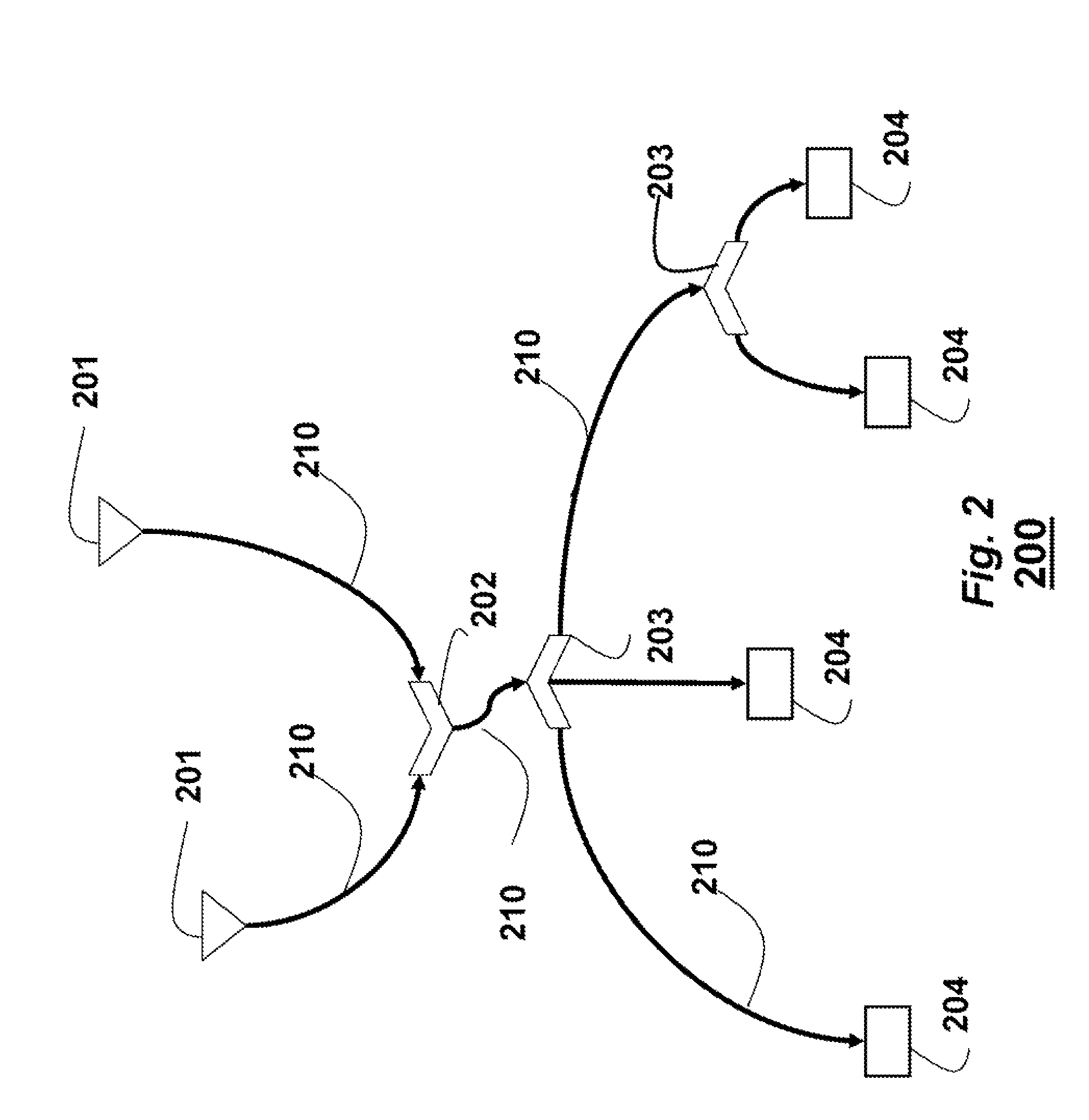
A method and system tracks models and predict object movement in an environment. Sequences of temporally and spatially adjacent events sensed by the set of sensors are linked to form a set of tracklets. Each tracklet has an associated starting and terminating location. The tracklets are used to construct a directed graph including starting nodes, terminating nodes, and, intermediate nodes connected by edges. The intermediate nodes can be split nodes where tracklets diverge onto different tracks, and join nodes where multiple tracklets converge onto a single path. Probabilities are assigned to the edges to model and predict movement of the objects in the environment.

Description

RELATED APPLICATION[0001]This application is a Continuation-in-Part of U.S. patent application Ser. No. 11 / 565,264, “Surveillance System and Method for Tracking and Identifying Objects in Environments” filed by Ivanov et al. on Nov. 30, 2006.FIELD OF THE INVENTION[0002]This invention relates generally to surveillance systems and object tracking methods, and more particularly to modeling and the movement of objects from surveillance data.BACKGROUND OF THE INVENTION[0003]Video cameras and relatively simple sensors make it possible to construct mixed modality surveillance systems for large environments. Although the sensors cannot identity objects, the sensors can detect objects in a relatively small area. The identification can be done from the images of videos acquired by the cameras when the images are available.[0004]Storage for videos acquired by such systems can exceed many terabytes of data. Obviously, searching the stored data collected over many months for specific objects, in...

Claims


Application Information

Patent Timeline
Patent Type & Authority Patents(United States)
IPC IPC(8): H04N7/18G06V10/84
CPCH04N7/18G06K9/6296G06K9/00771G06V20/52G06V10/84G06F18/29
Inventor WREN, CHRISTOPHER R.IVANOV, YURI A.SOROKIN, ALEXANDERBANGA, ISHWINDER KAUR
Owner MITSUBISHI ELECTRIC RES LAB INC
Learn More