Card connector

Inactive Publication Date: 2012-04-10
CHENG UEI PRECISION IND CO LTD
View PDF17 Cites 3 Cited by
  • Summary
  • Abstract
  • Description
  • Claims
  • Application Information

AI Technical Summary

Benefits of technology

[0006]As described above, the card connector of the present invention utilizes the monitoring terminal to be shared by the first switch terminal and the second switch terminal so as to respectively monitor whether

Problems solved by technology

Furthermore, it takes a rela

Method used


Image

  • Card connector
  • Card connector
  • Card connector

Examples


Embodiment Construction

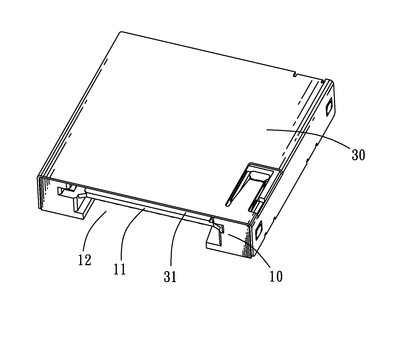
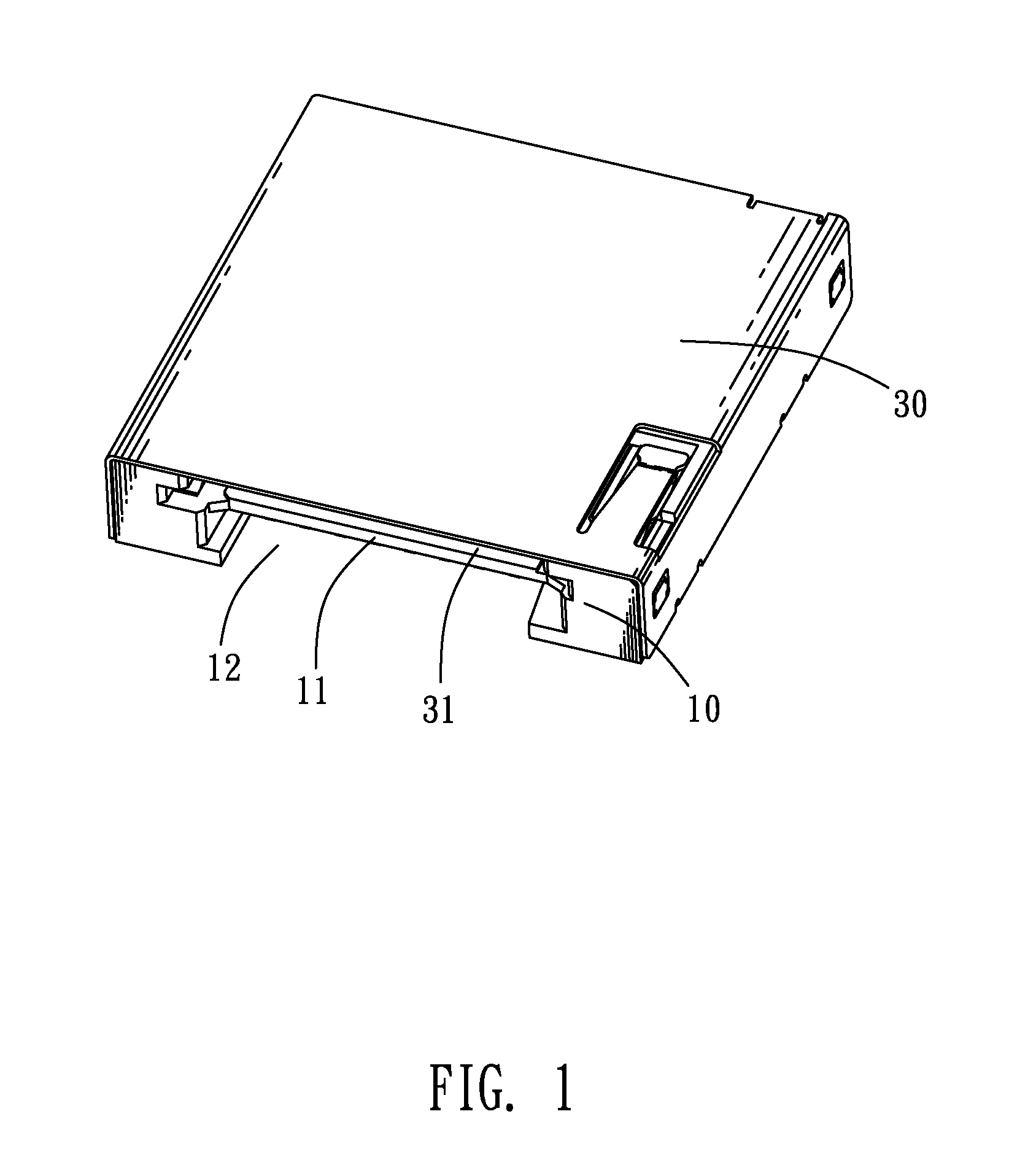
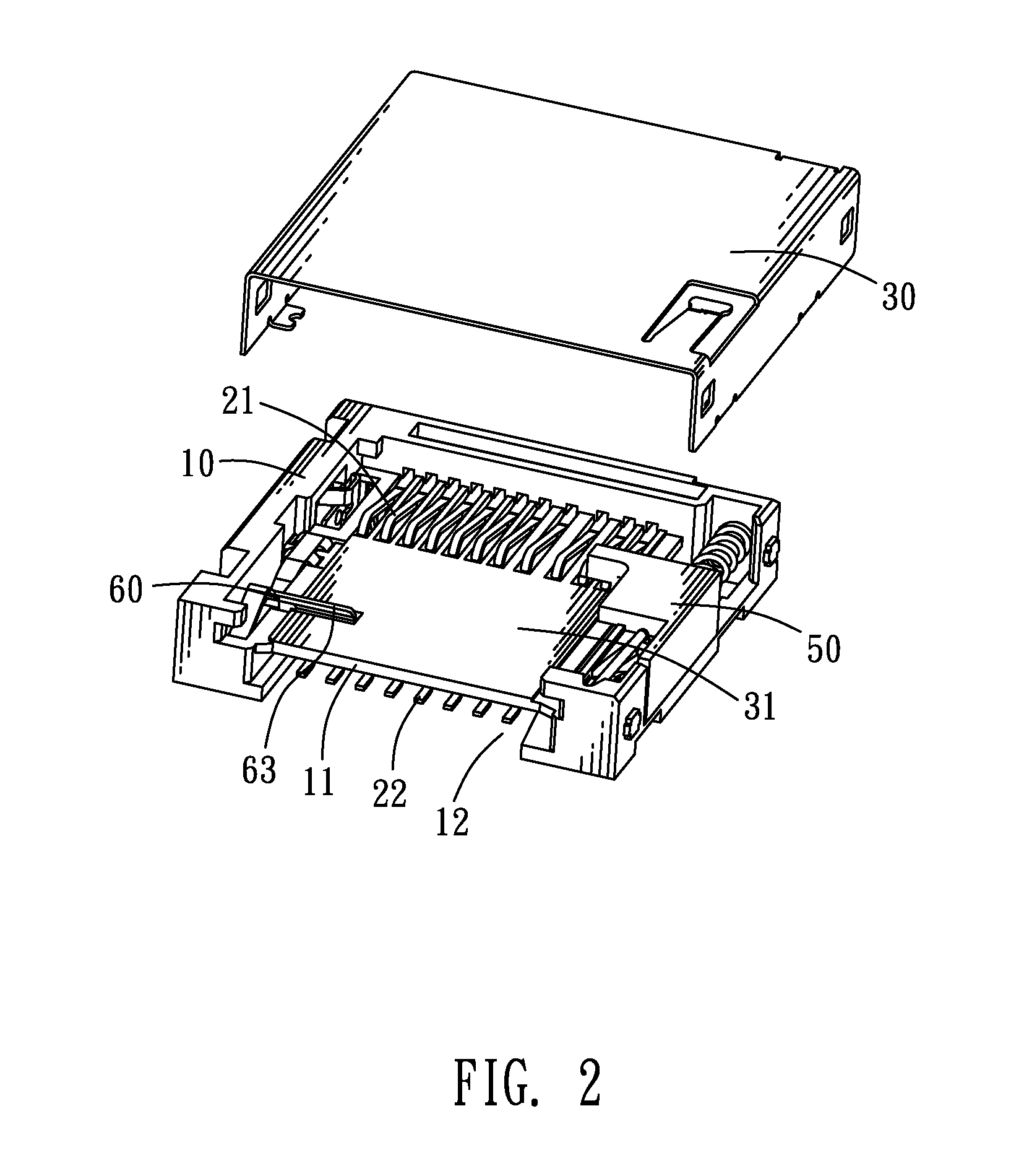
[0013]Referring to FIG. 1 and FIG. 3, a card connector in accordance with an embodiment of the present invention includes an insulating housing 10, a plurality of first electrical terminals 21 and second electrical terminals 22, a monitoring terminal group 40, an ejecting device 50, a fool-proofing member 60 and a cover 30.

[0014]Referring to FIG. 1, FIG. 3 and FIG. 4, the insulating housing 10 has a rectangular base board 101, a rear wall 102 protruding upward from a rear end of the base board 101, and two opposite side walls 103 protruding upward from two opposite side edges of the base board 101 and connected with two ends of the rear wall 102. A rectangular partition 11 extends forward from a substantial middle of an inside of the rear wall 102 and apart parallel to the base board 101 to define a second receiving chamber 12 therebetween so as to receive a second electronic card (not shown) therein. A bottom of one side wall 103 has a substantial middle concaved upward to form a f...


PUM


Abstract

A card connector includes an insulating housing defining a first receiving chamber and a second receiving chamber, a monitoring terminal fastened in one side of the insulating housing and having a contact plate, a first switch terminal fastened in the one side of the insulating housing and having a first pressing arm slantwise extending into the first receiving chamber and a first contact portion formed at a distal end of the first pressing arm for elastically contacting the contact plate by means of pressing the first pressing arm sideward, and a second switch terminal fastened in the one side of the insulating housing and having a second pressing arm slantwise stretching into the second receiving chamber and a second contact portion formed at a distal end of the second pressing arm for elastically contacting the contact plate by means of pressing the second pressing arm sideward.

Description

BACKGROUND OF THE INVENTION[0001]1. Field of the Invention[0002]The present invention relates to a card connector, and more particularly to a card connector capable of receiving two kinds of different electronic cards therein.[0003]2. The Related Art[0004]With the development of electronic technology, various electronic cards are widely used in electronic products, such as digital cameras, personal digital assistants (PDA) and mobile phones etc. The conventional electronic product defines a card connector so as to receive an electronic card therein. At present, the card connector is improved to often receive two or more kinds of different electronic cards. However, when each kind of electronic card is inserted into the card connector, a group of monitoring terminals is needed to monitor whether the corresponding electronic card is inserted in the card connector in place or not. As a result, the insertion of different kind of electronic card need be monitored by different group of mo...

Claims


Application Information

Patent Timeline
IPC IPC(8): H01R29/00
CPCG06K7/0073H01R12/7094H01R27/02
Inventor QU, ZHI-CHENGYANG, BING-TAOWU, YIN-LUNGCHEN, MING-CHIANG
Owner CHENG UEI PRECISION IND CO LTD
Why Eureka
Try Eureka